
NonStop S-Series Hardware Installation and FastPath Guide (G06.25+)

Configuring the System
HP NonStop S-Series Hardware Installation and FastPath Guide—529443-001
10-11
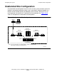
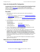
Create a Cascading Ethernet Switch Configuration
Create a Cascading Ethernet Switch Configuration
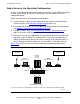
When no ports are left on the Ethernet switches or hubs in the operating configuration,
you can expand the configuration by cascading two additional Ethernet switches or
hubs online. Figure 10-8 shows a cascading Ethernet switch configuration.
A cascading Ethernet switch configuration containing more than four switches or hubs
is not supported for LAN configurations.
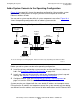
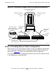
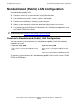
Figure 10-7. Connections for Adding a Server to the Operating Configuration
VST536.vsd
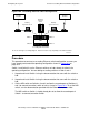
Ethernet Switch 1 Ethernet Switch 2
To Primary
System
Console
To Backup
System
Console
Cascade
Port
Cascade
Port
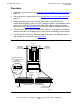
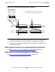
Medium-Dependent
Interface (MDI) Switch
(Setting for Ethernet Switch)
MDI
To
Ethernet
Switch
To PC
MDI-X
Group 01 Processor Enclosure
(Service Side)
PMF CRU Containing
Processor 0
Slot 50
PMF CRU Containing
Processor 1
Slot 55
Note: Connections vary
depending on the
Ethernet switch you use
To Ethernet Port
of PMF CRU
in Slot 55
To Ethernet Port
of PMF CRU
in Slot 50