
NonStop S-Series Operations Guide (G06.29+)


Determining Your System Configuration
HP NonStop S-Series Operations Guide—522459-009
2-10
Locating System Components in an Enclosure
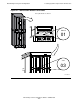
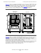
Figure 2-4 shows an example of a NonStop S-series I/O enclosure. IOMF 2 CRUs look
slightly different from the IOMF CRUs shown installed in slots 50 and 55 in the figure.
Also, if IOMF 2 CRUs are present, power supplies are installed at the bottom of the
enclosure in slots 31 and 32, below the fans. See Figure 2-3 on page 2-8.
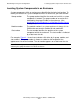
Figure 2-5 shows an example of NonStop IOAM enclosures in a system rack. Note that
each IOAM enclosure contains two I/O adapter modules (IOAMs), two ServerNet
switch boards, and slots for up to 10 Fibre Channel ServerNet adapters (FCSAs) or 10
Gigabit Ethernet 4-port ServerNet adapters (G4SAs).
The form factor of this type of enclosure differs radically from that of the processor and
I/O enclosures. IOAM enclosures contain no CRUs. None of the components are
replaceable by customers and are therefore FRUs.
Figure 2-4. NonStop S-Series I/O Enclosure Organization
Group
Module
794CDT .CDD
Appearance Side
Service Side
(Door Open)
Slots
50 55
51 52
53 54
56
01 02 03 04 05 06 07
08
11 12 13 14 15 16 17 18
09
10
19
20
21 22
28
27
2625
24
23