
NonStop S-Series Planning and Configuration Guide (G06.29+)

System Components
HP NonStop S-Series Planning and Configuration Guide—523303-021
4-5
Disk Management
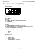
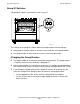
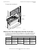
The faceplate of a disk drive includes:
•
A write-on label and a part number/barcode label
•
A green LED at the top that, when lit, indicates that the disk drive is operational.
•
A yellow or amber LED on the lower half that indicates disk activity.
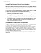
Disk drive slots are divided between two SCSI buses.
SCSI buses connect to ServerNet addressable controllers (SACs) on the multifunction
I/O boards (MFIOBs) on the processor multifunction (PMF) customer-replaceable units
(CRUs) and I/O multifunction (IOMF) CRUs. Each SCSI bus is terminated on both
ends.
For fault tolerance, the two disk drives of a mirrored volume must be installed in slots
that are on different SCSI buses. Two adjacent disk drive slots are on different SCSI
buses.
For disk drive requirements for 16-GB processors, refer to Disk Drives for 16-GB
Processors on page 8-4.
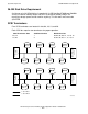
Disk Management
Location of the System Disks
Beginning with the G06.06 RVU, you can install the two disk drives of the mirrored
volume $SYSTEM in any two slots in the group 01 enclosure. That is, $SYSTEM-P can
be installed in a slot other than slot 11, and $SYSTEM-M can be installed in a slot
other than slot 12.
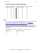
However, if you want to install the system disks in slots in other than 11 and 12, you
must install the disks in slots that have the same SCSI ID number. If the system disks
are located in slots with different SCSI IDs, the system halts. You can use any of these
pairs of slots for the system disks:
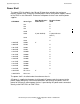
SCSI Bus Number Disk Drive Slots
1 02, 04, 06, 08, 12, 14, 16, 18
2 01, 03, 05, 07, 11, 13, 15, 17
SCSI ID Primary Slot Mirror Slot (page1of2)
01112
11314
21516
31718
41 2