
NonStop S-Series Planning and Configuration Guide (G06.29+)

System Components
HP NonStop S-Series Planning and Configuration Guide—523303-021
4-37
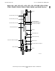
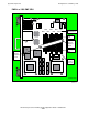
Processor Multifunction (PMF) CRUs
•
DC power cable
In S7400, S7600, S7800, S7800B, and Sxx000 processor enclosures, the
DC power cable supplies DC power and other signals to the PMF CRU from the
power supply in the power shelf. The DC power cable extends from the power
interface board (PIB), located on the power shelf bulkhead, to the DC power cable
receptacle on the PMF CRU.
•
DC power cable receptacle
On S7400, S7600, S7800, S7800B, and Sxx000 PMF CRUs, the 50-pin DC power
cable receptacle receives the DC power cable from the power supply.
The DC power cable is held in place by jackscrews. While the DC power cable is
connected to a PMF CRU, the PMF CRU cannot be removed from its enclosure. A
power interlock, located below the DC power cable receptacle, prevents this
removal.
Power-On Push Button, Cable, and Receptacle
Power-on cables connect all enclosures in a system in series. To power on the entire
system, you press the power-on push button on any PMF CRU or IOMF CRU in the
system. The power-on cable sends the power-on signal to all the other PMF CRUs and
IOMF CRUs in the system. Some examples of power-on cabling are located in Power-
On Cables on page 7-10.
The power-on cables connect to the RJ-11 power-on cable receptacles on PMF CRUs
and IOMF CRUs.
LEDs
The PMF CRU contains:
•
An amber fault LED, that when lit, indicates that the PMF CRU is in an error
condition.
•
A green power-on LED, that when lit, indicates that the PMF CRU is operational.
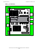
Processor and Memory Board (PMB)
All data processing and storage takes place on the PMB, which contains:
Processors
A pair of processors located on the PMB processes data and instructions. These
processors run in lock-step to ensure data integrity.