
NonStop S-Series Planning and Configuration Guide (G06.29+)

System Components
HP NonStop S-Series Planning and Configuration Guide—523303-021
4-71
Group, Module, and Slot Hierarchy for IOAM
Enclosures
For power and environmental requirements, planning, installation, and emergency
power-off (EPO) instructions for the R5500 UPS, refer to the documentation shipped
with the UPS.
For information about planning for a site UPS, contact your HP trained service
provider.
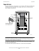
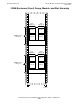
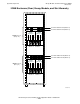
Group, Module, and Slot Hierarchy for IOAM Enclosures
Hardware in an IOAM enclosure is organized according to group, module, and slot
hierarchy:
To perform software or hardware operations using SCF or OSM, you must be familiar
with the organization and naming conventions and know how to identify individual
components within an IOAM enclosure. For example, OSM displays the location of a
fan in group 11, module 3, slot 17 in this form:
Fan (11.3.17)
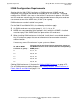
Term Definition
Group The IOAM enclosure and all the components within it. IOAM enclosures are
numbered in the same way as I/O enclosures.
Module One logical module. There are two logical modules (module 2 and module 3)
in an IOAM enclosure. Each logical module contains:
•
ServerNet switch board
•
Two power supplies
•
Two fans
•
Up to five ServerNet adapters (FCSA or G4SA)
Each module is numbered according to the fabric it supports:
•
Module 2 (X fabric)
•
Module 3 (Y fabric)
Note. Both module 2 and module 3 are supported by the X and Y fabrics.
The X fabric connection is through the ServerNet switch board in module 2,
slot 14 and the Y fabric connection is through the ServerNet switch board in
module 3, slot 14. All adapters in modules 2 and 3 have connections to both
the X and Y fabrics.
Slot A physical space in the IOAM module in which a component can be installed.
Slot numbers are assigned per logical module:
Slot # Component Page
1, 2, 3, 4, 5
14
15 and 18
16 and 17
ServerNet adapter
ServerNet switch board
Power supplies
Fans
4-69
4-69
4-70
4-69