
NonStop S-Series Planning and Configuration Guide (G06.29+)
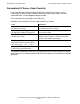

Completing the Installation Plan
HP NonStop S-Series Planning and Configuration Guide—523303-021
13-10
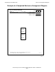
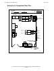
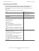
Floor Plan
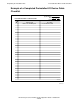
Example of a Completed Floor Plan
POWER
RECEPTACLES
Floor Plan
System Name
/ /
Date
Building Room
Scale: 1/4 inch = 1 foot
Desk (A)
Chair
File
Table
Cabinet
Chair
Chair
System
Console
(Primary)
Service
Appearance
System
Enclosure
Service
Appearance
System
Enclosure
Ethernet
Hubs
COMM LINES
EXIT
I/O CABLES
TO OTHER
ROOMS EXIT
HERE
TAPES
PRE-INSTALLED
ETHERNET
SUPPLIES
Cabinet
Shelves (A)
modem
System
Console
(Backup)
modem
Group 2
Group 1
power
Group 2
power
Power for
future
system
enclosures
7159
Pedestal
5190
$Tape1
7159
Pedestal
5170
$Tape0
SWAN
Group 1
Hubs
Hub
Hub
5 2239
\Case1
07 22 96
VST226.vsd
VST315.vsd