
NonStop S-Series Planning and Configuration Guide (G06.29+)

VST387.vsd
G
Group
21
50
Group
22
Group
23
Group
24
Group
25
50
50
50
50
5
4
6
1
2
3
654
3
21
Group
02
SEB
53
SEB
51
Group
35
50
Group
34
Group
33
Group
32
Group
31
50
50
50
50
5
4
6
1
2
3
6
5432
1
Group
03
SEB
51
SEB
53
Group
74
50
Group
73
50
Group
72
50
Group
71
50
1
2
3
4
6
5
Group 07
PMF 50
SEB
51
50
Group
64
50
Group
63
50
Group
62
50
Group
61
Group 06
SEB
51
5
6
4
3
2
1
SEB
51
Group 05
1
2
3
4
6
5
50
Group
51
50
Group
52
50
Group
53
50
Group
54
SEB
53
Group
01
65
432
1
50
Group
15
50
Group
14
50
Group
13
50
Group
12
50
Group
11
Group
81
50
Group
82
50
Group
83
50
Group
84
50
50
Group
45
50
Group
44
50
Group
43
50
Group
42
50
Group
41
1
2
34
5
6
5
6
4
1
2
3
Group
04
SEB
53
SEB
51
Group 08
PMF 50
SEB
51
1
2
3
4
6
5
1
2
3
4
6
5
SEB
51
PMF 50
PMF 50
PMF 50
PMF 50 PMF 50
PMF 50
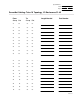
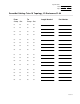
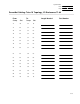
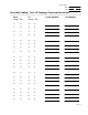
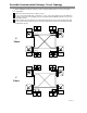
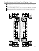
ServerNet Communication Pathways: Tetra 16 Topology, X Fabric
With a highlighter, shade the enclosures, ports, and slot numbers that are in use in your current configuration.
With a pen, black out the CRU you plan to remove.
If you are removing a PMF CRU, check this box. Then, on the worksheet for the Y fabric, black out the PMF CRU
in slot 55 in the corresponding enclosure to indicate that this PMF CRU will lose access to the X fabric as well.
On this worksheet, trace pathways of communication through all routers and ServerNet cables that connect to
the CRU you plan to remove. Circle all components and enclosures that will be affected by that CRU removal.