
NonStop S-Series Planning and Configuration Guide (G06.29+)

The ServerNet Communications Network
HP NonStop S-Series Planning and Configuration Guide—523303-021
2-3
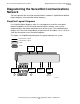
Diagramming the ServerNet Communications
Network
Diagramming the ServerNet Communications
Network
You can represent the ServerNet communications network in simplified and detailed
logical diagrams (also called ServerNet diagrams).
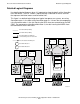
Simplified Logical Diagrams
Use simplified logical diagrams when it is not important to show the exact paths
between endpoints on the ServerNet communications network, such as when
diagramming the ServerNet architecture of an entire system. The simplified logical
diagram uses lines and shaded boxes to represent links and fabrics, so it is easier to
show the connections to the ServerNet adapters.
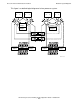
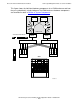
This figure is a simplified logical diagram of a typical two-processor system.
VST909.vsd
ServerNet link (Y fabric)
ServerNet link (X fabric)
X fabric
Y fabric
Ethernet
Disks
Y fabric
Processor
XY
Processor
XY
ServerNet
Adapter
ServerNet
Adapter
ServerNet
Adapter
ServerNet
Adapter
X fabric