
NonStop S-Series Planning and Configuration Guide (G06.29+)

The ServerNet Communications Network
HP NonStop S-Series Planning and Configuration Guide—523303-021
2-4
Detailed Logical Diagrams
Detailed Logical Diagrams
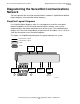
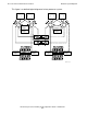
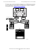
Use detailed logical diagrams when it is important to show the details of the ServerNet
links and routers. The X or Y fabric is represented by a collection of circles and lines
that represent individual routers and ServerNet links.
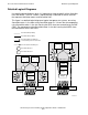
This figure is a detailed logical diagram of typical two-processor systems, one using
ServerNet router 1s, the other using ServerNet router 2s. It shows that for components
using ServerNet router 1, the slots housing the SEBs have one connection to the PMF
CRUs. For components using ServerNet router 2, the slots housing the MSEBs have
two connections to the PMF CRUs.
VST908.vsd
ServerNet link (X fabric)
ServerNet link (Y fabric)
ServerNet links for which the
connected objects are not shown
Unconnected ServerNet port
ServerNet Router 1
ServerNet Router 2
2
SEB
Processor
XY
Disks
Processor
XY
ServerNet
Adapter
ServerNet
Adapter
ServerNet
Adapter
ServerNet
Adapter
PMF CRU
SEB
MSEB
Disks
ServerNet
Adapter
ServerNet
Adapter
MSEB
ServerNet
Adapter
ServerNet
Adapter
2
2
Processor
XY
Processor
XY
PMF 2 CRU