
NonStop S-Series Planning and Configuration Guide (G06.29+)
Topologies
HP NonStop S-Series Planning and Configuration Guide—523303-021
3-9
Topology Configuration Considerations
Topology Configuration Considerations
Considerations for planning or changing the size or topology of your system:
•
Processors are always installed in pairs, two processors in each processor
enclosure.
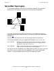
•
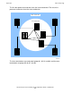
A Tetra 8 system can have one through four processor enclosures (two through
eight processors).
•
You can add processor enclosures to a Tetra 8 system until the maximum of four
processor enclosures (eight processors) is reached.
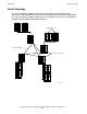
•
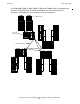
A Tetra 16 system can have one through eight processor enclosures (two through
sixteen processors).
•
You can add processor enclosures to a Tetra 16 system until the maximum of eight
processor enclosures (two through sixteen processors) is reached.
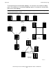
•
Processor enclosures must be added to a system in order by group number.
•
To change topologies, you must shut down the system. You might need to move
some cables or change some system configurations.
•
The NonStop S700 and other small size servers support only two processors, and
it can be configured only in the Tetra 8 topology. For more information, contact your
HP representative.
•
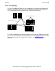
Two processor enclosures are connected together with a pair of ServerNet cables,
which connect a pair of SEBs or MSEBs in one enclosure and to a pair of SEBs or
MSEBs in the other enclosure.
•
An I/O enclosure is connected to a processor enclosure with a pair of ServerNet
cables, which connect a pair of SEBs or MSEBs in the processor enclosure to a
pair of IOMF CRUs or IOMF 2 CRUs in the I/O enclosure.
•
An IOAM enclosure is mounted in a standard 19-inch modular rack and connects
to the MSEB of S76000 and later NonStop S-series systems using multimode fiber-
optic cables (with LC-SC connectors) up to a maximum length of 125 meters. The
LC connector connects to the ServerNet switch board and the SC connector
connects to the MSEB.
•
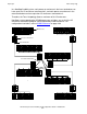
IOAM enclosures can replace any I/O enclosure in a system starting with G06.27,
and derive their group numbers from the Group I/O enclosures they displace. For
the G06.26 RVU, these restrictions apply:
•
IOAM enclosures (Groups 11, 12, 13, 14, or 15) are installed only in the inner
tetrahedron (Groups 01, 02, 03, and 04).
•
No I/O enclosure can be installed in the corresponding location Groups 02, 03,
or 04 as shown in this table: