
NonStop S-Series Server Description Manual (G06.24+)

TNS Execution Modes
HP NonStop S-Series Server Description Manual—520331-003
6-8
The Register Stack
The Register Stack
To maintain compatibility with other earlier systems, NonStop S-series processors
provide a register stack that is used mostly in nonaccelerated (TNS) execution mode.
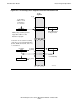
The register stack consists of eight 16-bit registers, designated R[0] (register stack,
element 0) through R[7]. See Figure 6-4. The register stack is where arithmetic
computations are performed and where most comparisons are made. Typically,
operands are loaded onto the stack, arithmetic operations are performed, the operands
are deleted, and a result is left on the stack. Three registers, R[5:7], also double as
index registers.
Usually, elements in the register stack are addressed implicitly. That is, an instruction
operates on the top element (or elements) without specifying an absolute register
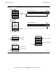
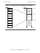
number. The current top element of the register stack is defined by the register stack
pointer, RP, shown in the upper part of Figure 6-5. RP, which is a three-bit field in the
Environment register, contains the register number, 0 through 7, of the top element.
The RP setting is incremented when operands are loaded onto the register stack and
decremented when arithmetic is performed or results are stored. The empty (or full)
state of the register stack is defined as RP = 7. There is no protection against rolling
over from 7 to 0 or from 0 to 7.
The elements in the register stack are named as to their location relative to the current
top element. As shown in Figure 6-5, the top element is designated “A”, the second is
“B”, and so on through “H”. These names have no fixed relationship to the register
numbers, and the naming sequence wraps around the end of the stack. In cases of
doubleword and quadrupleword operands, the low-order word is in A.
In the first example in Figure 6-5, because the register pointer in the Environment
register contains the value 3, the top of the register stack is R[3]. That register is
named A, and the next lower-numbered registers are named B, C, and so on, wrapping
around the end of the stack to H. In the second example, RP is 6, so A is R[6]. Three
examples of operand pairs on the register stack are also shown.
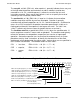
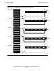
Figure 6-4. The Register Stack Accumulates Arithmetic Results
R [0]
R [7]
Register
Stack
Index Registers
(Optional Use)
VST269.vsd