
NonStop S-Series Server Description Manual (G06.24+)

TNS Execution Modes
HP NonStop S-Series Server Description Manual—520331-003
6-10
Register Stack Operations
Register Stack Operations
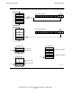
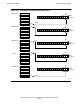
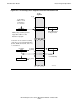
A typical operation to add two numbers in the register stack is illustrated in Figure 6-6.
The operation proceeds as follows: the operands are first loaded from global data (G)
into the register stack using LOAD instructions, then an IADD (integer add) instruction
is executed to perform the desired arithmetic, and finally the result is stored back into
memory using a STOR instruction. Grouped together to form a program, the operation
looks like this:
LOAD G + 002 !load data element G[2] onto register stack
LOAD G + 003 !load data element G[3] onto register stack
IADD !integer add
STOR G + 004 !store result from register stack into G[4]
Before the operations begin, as shown in the top diagram of the figure, the register
stack is assumed to be empty; RP indicates R[7].
In the second diagram, the value 5 is loaded from the global data area of the user data
segment (location G+002). The data item is loaded into the first available stack
register, R[0], and RP is incremented to point at this new top-of-stack register.
In the third diagram, the value 6 is similarly loaded from global data. This item is
loaded into the next available stack register, R[1], and RP is again incremented to point
at this register.
The fourth diagram reflects the condition of the register stack after an integer add
(IADD) instruction has taken place. Both operands have been logically deleted by
decrementing RP back by two elements (to R[7] again), and the result of the addition
has been loaded into the first available stack register. In this case, the first available
register is R[0], so the arithmetic result overlays the value that was formerly in R[0],
which was the first operand, the value 5. The second operand, the value 6, actually
remains in R[1], but because RP now indicates that the top of the stack is R[0],
anything in R[1] is logically an undefined value.
The fifth diagram reflects the condition of the register stack after the STOR G+004
instruction has taken place. The arithmetic result of the addition has been stored into
memory in global data location G+004, and the value has been deleted from the
register stack by decrementing the RP pointer back to 7. That again indicates the
empty state. Registers R[0] and R[1] still contain 11 and 6, but succeeding operations
will automatically overlay their contents.