
NonStop S-Series Server Description Manual (G06.24+)

TNS Execution Modes
HP NonStop S-Series Server Description Manual—520331-003
6-46
A Procedure’s Local Variables
A Procedure’s Local Variables
Unlike the global data area, which exists at all times during the life of the process, the
local data area for a procedure exists only during the time between the procedure’s
being called and its exiting.
One of the subdivisions of the local data area is used specifically for local variables.
These are found in a certain number of locations (up to 127) immediately succeeding
the stack marker. Because the L register specifies the ending location of the stack
marker, the local variables are addressed by positive displacements from the L register
setting.
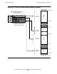
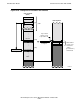
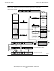
As indicated in Figure 6-26, the L-plus-relative addressing mode is specified by the bit
pattern of 10 in bits 7 and 8 of the instruction word. The seven-bit field consisting of
bits 9 through 15 specifies the word displacement from L. Either direct or indirect
addressing can be used, indicating that any location in the local variables area can
contain either a value (direct) or an address (indirect).
The local variables are allocated and initialized by instructions at the start of a
procedure’s code. Thus, a procedure can be called any number of times (and in fact
can call itself), and each call generates a fresh copy of the procedure’s local variables
area.
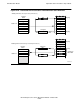
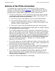
In the example illustrated in the figure, assume there are three local variables declared
in a TAL source program: “i” is a one-word uninitialized variable, “j” is a one-word
variable initialized with the value 5, and “k” is an indirectly addressed array variable
consisting of 32 words. The instructions to generate these variables are:
ADDS +001 ! Add to S (make room for i)
LDI +005 ! Load Immediate (initialize j
LADR L+004 ! Load Address and
PUSH 711 ! PUSH to Memory pointer to k)
ADDS +040 ! Add to S (allocate space for k)
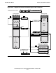
The first ADDS instruction increments the S register setting by 1. This allocates one
word for the variable “i”.
The LDI instruction puts the initialization value for “j” (5) on the top of the register stack.
The LADR instruction calculates the G-relative address of the first word of the indirect
array “k” and puts the address on the top of the register stack.
The PUSH instruction performs two functions: (1) it puts the initialization value given in
“j” and the address of the array “k” into L[2] and L[3] of the process’s stack,
respectively, and (2) it increments the S register setting by 2 to allocate the two words
needed for “j” and the address pointer to “k”.
The last ADDS instruction increments the S register setting by 32 (octal 40). This
allocates 32 words for the indirect array “k”.