
NonStop S-Series Server Description Manual (G06.24+)


Input/Output Operations
HP NonStop S-Series Server Description Manual—520331-003
10-8
I/O Process Models for Storage I/O
I/O Process Models for Storage I/O
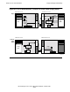
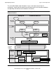
Figure 10-4 shows two I/O process models. Both models use the conventional
process-pair arrangement of I/O processes that is used in all NonStop servers,
including those prior to the NonStop S-series servers. Those earlier servers, however,
required the I/O process and its backup to be in the two processors which interfaced to
the two I/O buses that connected to the relevant I/O controllers.
In the ServerNet case (NonStop S-series servers), the standard I/O storage model can
still be used, but the restriction of locating an I/O process and its backup in adjacent
processors is removed. This freedom of location happens because there are no I/O
buses in the ServerNet architecture. However, for the sake of speed and efficiency, the
I/O processes are usually located in processors that are in the same enclosure as the
relevant I/O controllers.
In the first case (standard I/O storage model), note that the I/O process for this
example is located in processor A. Its backup is located in processor B. To perform an
I/O operation through this I/O process, client processes in processors B, C, and D must
send their request through the message system (as described in Section 9,
Interprocessor Communication) and ServerNet hardware to the I/O process in
processor A (note lighter-weight lines).
Each client in this case has its own buffer space, including the client shown in
processor A. However, the I/O process must transfer data to and from the controller
using its own buffer (note darker line connecting to the controller), and clients must
transfer the data to and from the I/O process’s buffer (the other dark lines). For
processors B, C, and D, this means additional transfers through the ServerNet
hardware.
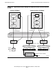
As an improvement on the process pair model, a direct bulk I/O transfer model (lower
part of Figure 10-4) is possible (not available in G02.00 release). This model still
requires each client to communicate with the primary I/O process to start the I/O
transfer, but the data is transferred directly between the controller and the client’s
buffer without needing to go through a separate IOP data buffer. This path saves
numerous ServerNet transfers.
In the direct bulk I/O example in Figure 10-4, the primary I/O process is located in
processor C, and its backup is in processor D. To begin an I/O transfer, the client in
processor A sends a read or write request to the I/O process (1). The I/O process then
initiates the transfer by sending appropriate commands to the controller (2), including
the ServerNet address of the client buffer in processor A. The controller, using the
supplied address, assumes control of the operation, transferring data directly between
the client buffer in processor A and the storage device (3). When the transfer is
completed, the controller sends a completion notice to the I/O process (4), which in
turn interrupts the client to signify completion of the operation (5).