
NonStop S-Series Server Description Manual (G06.24+)

Introduction
HP NonStop S-Series Server Description Manual—520331-003
1-22
Multiple I/O Enclosures
Multiple I/O Enclosures
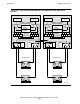
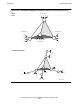
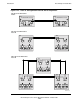
When two processor enclosures are interconnected in a basic configuration (using a
single pair of SEBs), they can each support two I/O enclosures. The resulting six
system enclosures are connected as shown in Figure 1-12. In this case, the router
ports from the SEBs serve two functions: they interconnect the ServerNet fabrics in the
two processor enclosures, and they provide external I/O access to two I/O enclosures.
In Figure 1-12, smaller blocks represent logic that was shown in detail in previous
topics. For example, the entire internal I/O structure for processor cabinets, shown in
detail in Figure 1-8 on page 1-15, is represented by a pair of ServerNet adapter blocks
and a pair of blocks divided into four parts that represent the four internal ServerNet
addressable controllers (SACs).
The I/O enclosure logic, shown earlier in Figure 1-10 on page 1-19, is even further
miniaturized to show eight enclosures in Figure 1-12. The only router connections
actually shown are those for the external connections to the routers in the SEBs in the
processor enclosures. The remaining five connections of each router are as previously
shown: one for each side of the four available ServerNet adapters (middle stack) and
the fifth one for the ServerNet bus interface (SBI, not shown) that interfaces to the four
SACs that are on each multifunction I/O board (MFIOB). Those four SACs, for the
SCSI bus, Ethernet, and so on, are represented by the blocks in the lower left and right
corners of the I/O enclosures.
In operation, note that each processor has two paths (either X or Y) to access any SAC
(which includes the ServerNet adapters) anywhere in Figure 1-12. That is possible
because of the SEB-to-SEB connection between the two processor enclosures. Each
passage through a router is a “router hop.” The hop count can vary from one to four in
this configuration.
Also note that it is not possible to cross over between X paths and Y paths. No matter
how extensive the ServerNet structure grows, the ServerNet fabrics for X and Y remain
separate and independent. Both are in simultaneous use at all times. A failure of a
ServerNet link between routers (or between a router and a SAC) affects only that
portion of the fabric. The remainder of the fabric remains fully functional. Operating
system software detects such link failures and provides automatic rerouting through
the opposite fabric whenever necessary.
In Figure 1-12, the configuration shown has ServerNet adapters in the processor
enclosures. However, in your own computing environment, those ServerNet adapters
can be replaced with pairs of additional SEBs instead. Such a configuration provides
much more I/O capability, as illustrated next.
Note. For simplicity, Figure 1-12 and Figure 1-13 show six-port routers in association with the
processors, thus resembling the configuration shown in Figure 1-7 on page 1-14. As shown in
Figure 1-8 on page 1-15, other NonStop servers have seven implemented router ports (instead
of six) and use two of them (instead of just one) to service the four internal SACs.