
NonStop S-Series Server Description Manual (G06.24+)


Introduction
HP NonStop S-Series Server Description Manual—520331-003
1-42
Split-Star Topology
Split-Star Topology
The split-star topology, introduced with the G06.12 RVU, supports up to 16 nodes and
is required for clusters using 6770 switches that have more than eight nodes.
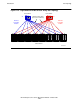
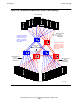
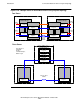
Figure 1-22 shows both fabrics of a 16-node ServerNet cluster connected in a split-star
topology.
The split-star topology uses up to four cluster switches—two for the X fabric (referred
to as X1 and X2) and two for the Y fabric (referred to as Y1 and Y2).
The first cluster switch on a fabric (X1 or Y1) supports ServerNet nodes 1 through 8.
The second cluster switch on the same fabric (X2 or Y2) supports ServerNet nodes 9
through 16.
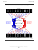
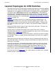
ServerNet clusters using either the split-star topology or the tri-star topology require
additional fiber-optic ServerNet cables to connect multiple cluster switches on each
fabric. These additional cables are shown in the central area of Figure 1-22 and
Figure 1-23.
In the split-star topology, the two cluster switches on each fabric are connected by a
four-lane link consisting of four fiber-optic cables. Ports 8 through 11 of the two cluster
switches are used for the four-lane link. Traffic travels in both directions across all four
lanes of the link.
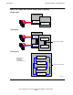
Cluster switches X1 and Y1 send traffic from ServerNet nodes 1 through 8 across the
four-lane links to cluster switches X2 and Y2 for routing to ServerNet nodes 9 though
16.
If one lane of a four-lane link is down, traffic between up to four nodes is affected on
one of the fabrics. For example, if port 8 is down at either end, ServerNet nodes 1 and
2 cannot communicate with ServerNet nodes 9 through 16 on the affected fabric, and
ServerNet nodes 9 and 10 cannot communicate with ServerNet nodes 1 through 8 on
the affected fabric.
Note. All four fiber-optic cables are required for a four-lane link, regardless of the number of
nodes in the split-star topology.