
NonStop S-Series Server Description Manual (G06.24+)

Introduction
HP NonStop S-Series Server Description Manual—520331-003
1-48
Connections Between Zones in Layered Topology
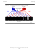
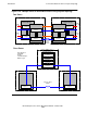
Connections Between Zones in Layered
Topology
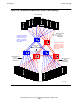
The layered topology described in the preceding topic can be extended to consist of
two or three switch zones. Figure 1-25 illustrates these cases.
A switch zone comprises a pair of X and Y cluster switch groups and the ServerNet
nodes connected to them. For simplicity, Figure 1-25 does not show the nodes
although the two-zone illustration does identify the numbering of the connected nodes.
The three-zone illustration includes outline shapes for the four layers in zone 1, but
omits them in the other zones. All zones must have exactly the same number of
layers.
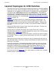
A maximum of 64 nodes is possible for two zones. For three zones, connections for up
to 96 nodes are physically possible, but HP currently supports no more than 64 nodes.
HP recommends two zones for best fault tolerance, but three zones can provide
ServerNet nodes at three different locations.
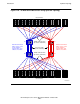
Switch zones are interconnected with zone-to-zone fiber-optic cables, and are
arranged so that layer 1 switches connect only to layer 1 switches, layer 2 switches to
layer 2 switches, and so on. As usual, there are separate X and Y paths.
In the two-zone case, four cables connect each pair of corresponding switches in the
two zones. In the three-zone case, two cables connect in a similar manner to each
neighboring zone.