
NonStop S-Series Server Description Manual (G06.24+)

Principles of System Operation
HP NonStop S-Series Server Description Manual—520331-003
2-10
Sequence for Outgoing Requests
Sequence for Outgoing Requests
This topic and the next one describe in more detail the BTE operations outlined in the
preceding topic. (Then the final two topics describe the AVT.)
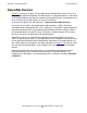
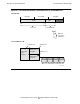
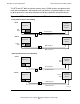
Figure 2-5 illustrates the sequence of events for locally initiated read and write
requests. The only difference for the read and write sequences is that data (D) is not
included in read requests. The following steps correspond to the numbered callouts in
the figure.
1. A client process (such as an I/O process or the message system) initiates a
request by first building a transfer information block (TIB) in memory. A transfer
information block consists of a header and one or more buffer descriptor
structures.
2. Once the TIB is completed, it defines the virtual addresses for the buffer that is to
be the source of write data or the destination of incoming read data.
3. The client process now invokes ServerNet services, supplying the location of the
TIB.
4. The ServerNet services, using information from the TIB, builds a linked series of
BTE descriptors for the use of the block transfer engine. These descriptors
contain the (translated) physical addresses of the client’s buffer (one descriptor for
one page), along with other necessary transfer information.
5. ServerNet services now passes control to the hardware of the BTE engine,
supplying the location of the BTE descriptors.
6. The BTE hardware gets information from the BTE descriptors to build the header
of the outgoing packet (H) and the address in the target ServerNet device (A) that
is applicable for reading or writing the data.
7. The BTE hardware completes the outgoing packet. In the case of a write request,
the BTE hardware uses DMA and the supplied physical addresses to include data
(D) in the packet.
8. The BTE hardware sends the completed packet through the processor ServerNet
interface to the connected port of the processor’s router, thus beginning
transmission to the target ServerNet device.
At this point, the BTE hardware updates internal registers for byte count and address,
and then proceeds to the next packet until the byte count is exhausted.