
NonStop S-Series Server Description Manual (G06.24+)


Principles of System Operation
HP NonStop S-Series Server Description Manual—520331-003
2-14
Sequence for Incoming Requests
Sequence for Incoming Requests
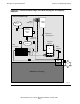
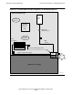
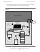
Figure 2-7 illustrates the sequence of operations for an incoming request, one that did
not originate in this ServerNet device. In this case, the remote access logic is used
instead of the transfer initiation logic (shaded out) that was used in Figure 2-5 and
Figure 2-6.
1. Prior to being able to handle incoming requests, an access validation and
translation table must have been set up, as well as buffer space for each
ServerNet device that can possibly make requests to this (illustrated) device. The
example shown arbitrarily assumes that “device 3” is sending the request. Thus
ServerNet services will have set up the access validation and translation table
(AVTT) for that device. Entries in the AVTT contain information for virtual-to-
physical address translation.
2. The incoming request packet is received by the processor ServerNet interface.
Upon examining the header of the packet, the processor ServerNet interface
determines that this is a request packet. It is unexpected in the sense that this
device (specifically the BTE logic) did not originate this transaction. The processor
ServerNet interface therefore passes control to the access validation and
translation (AVT) hardware.
3. The AVT hardware accesses the AVTT to determine whether the address supplied
in the header of the packet is valid—that is, that it actually addresses some
location in the buffer space allocated for “device 3.” Virtual addresses are being
compared at this time.
4. If the access is valid, the AVT hardware reads the table entry information and
translates the address supplied by the packet into a physical address. The AVT
hardware at this point also returns a response packet (see next topic). If the
access is not valid, the response packet includes a negative acknowledge in the
header.
5. If the incoming valid request is a write request, the AVT hardware writes the packet
data into the addressed locations within whatever buffer space allocated for
“device 3.” The addressed locations may be an in-request buffer, as shown, or in
some cases can be the client’s buffer.
6. If a dedicated in-buffer is used, the client process periodically must copy the data
to its own (or some other) buffer.
7. If the incoming request address is valid but addresses a particular location that has
been agreed upon as an interrupt location (the AVTT entry at that location has its
interrupt bit set on), the packet is placed in an interrupt queue. A typical reason for
doing this might be to signify that all packets for the current request have been
exchanged.
8. In queue order, the packet is examined by exception-handler millicode, and the
appropriate interrupt is passed up to a higher-level interrupt handler.