
NonStop S-Series Server Description Manual (G06.27+)


TNS Execution Modes
HP NonStop S-Series Server Description Manual—520331-004
6-12
The Register Stack in Memory
The Register Stack in Memory
As implemented in the NonStop S-series processor, the register stack (in TNS mode)
consists of eight dedicated locations in virtual memory, rather than eight physical
hardware registers. The location for this simulated register stack is found in the last
segment of every user data space. (Region 63 is a shared region among all
processes.) Therefore, in those cases where it is necessary to preserve the contents
of the register stack when one process is temporarily suspended to dispatch another,
the contents are saved in the process control block (PCB) of the suspended process.
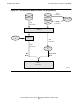
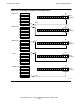
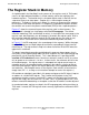
Figure 6-7 shows the structural layout of the register stack in virtual memory. The
register stack is located in a single page, called the RP wrap page. The current
execution mode flag (TNS, accelerated, or native), is also kept in the same page as the
register stack, but the primary use of the page is to contain the register stack. A bit in
the execution mode flag indicates whether the RP wrap registers are valid (in use).
They are valid in TNS mode and in accelerated mode during mode transitions.
In Figure 6-7, the RP wrap page is the second page in the segment. Within that page,
the eight RP registers are kept at byte offset 0 and at succeeding 512-byte intervals
from there on. The register data is kept in the lower half of the 32-bit RISC word; the
upper half is undefined.
The pages immediately preceding and following this page are absent pages; that is,
every entry in the segment page tables for these segments has the Valid indicator flag
permanently set off (meaning absent). This is done because it is possible for RP
overflow or RP underflow to occur, wherein an attempt is made to set RP to a value
of 8 or greater or to a value of –1 or less. In those cases, the reference will fall in one
of the absent pages. If a register access is attempted to a register out of range, an
exception occurs; the exception handler recognizes the address as being on one of
those two special pages, adjusts the register pointer by 8 in the appropriate direction,
and continues. (No exception occurs as the register stack switches to and from the
empty state, RP = -1, as long as no instruction attempts to access the registers.)
RP overflow or underflow is possible in this processor because the RP index is kept as
an address in a 32-bit RISC register. That is unlike the RP pointer in the TNS
architecture of earlier systems, in which RP is merely a 3-bit field in the Environment
register and simply rolls over from 0 to 7 or from 7 to 0. In NonStop processors, such
rollovers need to be detected by an exception so that the RP address can be adjusted.
In accelerated mode, registers are kept in the RP wrap page only during transitions to
TNS mode. Instead, the TNS register values currently significant are retained in RISC
registers.