
NonStop S-Series Server Description Manual (G06.27+)


TNS Execution Modes
HP NonStop S-Series Server Description Manual—520331-004
6-76
Mapping Return Addresses and Debug Points
Mapping Return Addresses and Debug Points
The purpose of the Pmap table is to map TNS P addresses in a given TNS code
segment of an accelerated code file to corresponding RISC PC addresses. In theory,
that could result in a large table (64K words, or 256 KB, for each TNS code segment).
In addition, two tables are really needed: one to map return addresses for procedure
returns and one to map debug points.
This topic explains how an efficient encoding of the Pmap table allows two logical
tables to be combined into one and overall size to be only 96 KB. However, the details
are not essential to comprehension of the overall function and may safely be skipped.
The part of the table that maps return addresses is called the Rmap. The Rmap maps
a “safe” TNS address to its corresponding RISC address. Safe points are called
register-exact points. These are places in the accelerated program at which control
can safely transfer from nonaccelerated to accelerated execution mode (or during
returns, can stay in accelerated mode). The part of the table that maps debug
addresses is called the Dmap. The Dmap maps a TNS memory-exact point (usually
a statement boundary) to its corresponding RISC address. Most register-exact points
are also memory-exact points; thus a single table for both maps is practical.
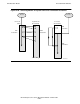
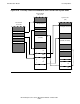
For compactness of the table, full 32-bit addresses are actually entered only for the
start (or base) of groups of eight TNS addresses. The drawing in the top left area of
Figure 6-41 shows an example of such a group. Because the range of addresses
shown is 16 through 23, this would be the third group in the table. (Though called P
values, these are C-relative addresses.) Assume for this example that P = 19 is a
register-exact point and P = 22 is a memory-exact point.
The diagram at top right assumes that 33 RISC instructions resulted from accelerating
the TNS code. (The correspondence of TNS-to-RISC instructions is simplified.) The
base for this group is the first usable map point (for P = 19), which is assumed to be
RISC address %h 70420128. The next map point (for P = 22) is offset eight
instructions from this base. The Pmap table provides RISC addresses for both points.
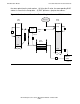
The Pmap table, as shown, consists of two arrays back-to-back, with the midpoint
taken as the base of both. The base address is found by indexing negatively (divide
19 or 22 by 8, to arrive at the third entry). Offset values are found in groups of eight
specially encoded individual bytes, and the specific group is found by indexing forward
from the midpoint (note highlighted group for the example). The most significant bit of
each byte specifies whether the entry is an Rmap entry (0) or a Dmap entry (1), with
certain values having reserved meanings (all ones, or %h FF, means no entry). The
remaining seven bits specify the offset—in this case %h 00 and 08 (ignoring the high-
order bit). Shifted by two to produce a byte address, these offsets become 00 and 20,
respectively. When added to the base, the addresses are %h 70420128 and
70420148.