
NonStop S-Series Server Description Manual (G06.27+)

Interprocessor Communication
HP NonStop S-Series Server Description Manual—520331-004
9-8
Message Transfer Mechanisms
Message Transfer Mechanisms
Referring back to Figure 9-1 on page 9-3, which showed the four levels of protocol that
are involved in interprocessor communication, three have at this point been described.
The ServerNet hardware protocol was covered in Section 2, Principles of System
Operation, and the linker-listener and message system protocols were covered in the
preceding two topics. The remainder of this section describes the fourth, remaining
protocol. This topic and the next one provide some basic information, and the four final
topics provide specific sequences for transferring messages through the network.
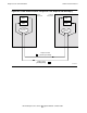
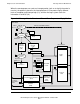
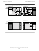
Figure 9-4 shows the mechanisms involved in message transfers between processors.
Later illustrations in this section use simplified representations of the details shown
here. Refer back to this figure whenever you need clarifying detail.
Whenever a client process (which could be either a linker or a listener) needs to send a
message, it uses the mechanisms denoted by the numbers 1 through 6 in the figure.
The client (1) is reponsible for allocating some buffer space for the communication. (In
addition to these buffers, the message system has setup buffers that it maintains in its
own setup areas.) Then the client uses the linker-listener protocol to invoke the
message system (2) to begin the message transfer.
The message system creates a transfer information block (TIB) (3), and calls
ServerNet services (4) to assume control. ServerNet services translates the virtual
addresses in the TIB to physical addresses as a linked list of BTE descriptors (5). Then
ServerNet services passes control to the hardware of the block transfer engine, or BTE
(6). The BTE manages (or at least starts to manage) the physical transfer of
information to and from the client buffers, transmitting and receiving such information
over the ServerNet hardware to and from the buffers of the corresponding process in
the target processor. However, for some kinds of transfers (as shown later), the target
processor could switch roles, so that it actually performs the pulling or pushing of data
with its own BTE.
Depending on the kind of transfer and particular phase of the transfer, the BTE can
either push data from the buffers (7) or pull data into the buffers (8 and 9). Pushing
data involves either request control and request data, or reply control and reply data.
Pulling of data by the BTE is for request control and data only, and follows one of the
two paths shown, depending on the combined size of the control and data. If the
combined size will fit into the readlink cache (which does not require address
translation), the control and data are stored there (8) for later copying to the client
buffers. Otherwise, the data is stored directly into the addressed buffers (9).
When the processor receives a ServerNet transmission that originated at another
node, that transmission is handled by the access validation and translation (AVT)
hardware. The AVT stores the data wherever specified in the ServerNet packets. Short
messages, such as those consisting only of control information, are usually addressed
to and stored in one of four pre-push buffers (10). Longer messages, such as reply
information with combined control and data size exceeding 1920 bytes (current
specification), are addressed to and stored in the client’s reply buffers (11).