
NonStop S-Series Server Description Manual (G06.27+)

Introduction
HP NonStop S-Series Server Description Manual—520331-004
1-10
Fault-Tolerant Process Communication
Fault-Tolerant Process Communication
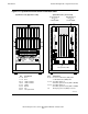
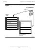
Fault tolerance for processes is accomplished by providing a backup process in
some other processor and providing two or more paths of communication between
them, so that if one path or processor should fail, the other processor and paths will
remain operable. This basic principle of fault-tolerant process communication is
illustrated in Figure 1-5.
In the example shown, process A can be assumed to be the primary process of a
process pair. The backup process, process B, is programmed to accept checkpoint
messages that convey significant changes in the state of the primary process. Upon
any failure of the processor that is executing the primary process, the backup process
can assume execution of the work from the point of the last valid checkpoint.
Dual data paths between the processes assure that checkpoint messages can still be
delivered in the event that one of the paths should fail. Note that process A can send
checkpoint messages to process B either through router X or through router Y. Thus if
a problem should occur on the MFIOB associated with processor 0, process A can still
send its checkpoint messages through the MFIOB associated with processor 1.
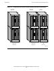
Although, for this example, the two processors are represented as being in the same
processor enclosure, in fact the fault-tolerant principle applies even if the primary and
backup processes are running in processors in different enclosures. The ServerNet
architecture is so designed that all X routers are connected together and all Y routers
are connected together. Thus process A can send its checkpoint messages to the Y
router in its own enclosure and be assured that, through a succession of other Y
routers, those messages will reach the backup process no matter where it is.
The complex interconnection of all routers into two parallel structures creates two
independent data-routing entities, each called a ServerNet fabric. The interconnection
of the X routers makes up the X fabric, and the interconnection of the Y routers makes
up the Y fabric.
Note. ServerNet routers differ in the number of ports available for routing. For example, IOMF
CRUs use the 6-port routers, whereas IOMF 2 CRUs use the 12-port router 2s. Generally, this
manual shows 6 ports for a router unless the illustration pertains specifically to hardware that
uses the 12-port router 2s.