
NonStop S-Series Server Description Manual (G06.27+)

Introduction
HP NonStop S-Series Server Description Manual—520331-004
1-26
Tetrahedral Topology
Tetrahedral Topology
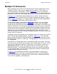
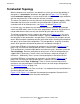
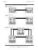
When more processor enclosures are added to a system, the core of the topology is
designed as a tetrahedron, idealized in the upper part of Figure 1-14. This design,
called tetrahedral topology, is used to minimize the number of router hops needed to
get from the processors in one enclosure to those in another.
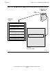
The routers illustrated here are only those on the ServerNet expansion boards (SEBs).
Remember that there also are routers on the multifunction I/O boards (MFIOBs)
associated with all of the processors; see Figure 1-9 through Figure 1-13.
In the ideal case, any processor can communicate with any other by going through
zero or two SEB routers (zero if in the same group of four). However, the ideal case is
not possible because there are only two external physical ports on the SEBs.
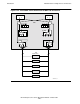
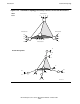
The actual arrangement used is shown in the lower part of Figure 1-14. In this case,
the first eight processors, numbered 0 through 7, connect directly to those routers at
the four points of the tetrahedron—two per router. That accounts for two ports of each
router. With three ports needed to connect to the other routers forming the tetrahedron,
one port is left to extend the configuration. This port provides a single link to another
router, which provides connection for processors numbered 8 through 15.
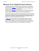
Using single SEB pairs in the processor enclosures (as illustrated in Figure 1-12 on
page 1-23), the maximum configuration possible is limited to the core tetrahedron.
That configuration is limited to eight processor enclosures and is therefore termed the
Tetra 8 topology. Because each procesor enclosure in a Tetra 8 configuration can
support two I/O enclosures, Tetra 8 servers are limited to a maximum of eight I/O
enclosures. Additionally, Tetra 8 servers cannot participate in ServerNet clusters.
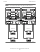
Using dual SEB pairs in the processor enclosures (as illustrated in Figure 1-13 on
page 1-25), the maximum configuration permits 16 processor enclosures and is
therefore termed the Tetra 16 topology. Tetra 16 servers can have up to 36 I/O
enclosures and can participate in ServerNet clusters for much larger configurations.
See ServerNet Clusters
on page 1-36.
The normal growth pattern for Tetra 16 servers is to complete the core tetrahedron first
and then expand on each corner.
Figure 1-15
to Figure 1-19 show how the conceptual arrangement illustrated in this
topic is implemented with actual ServerNet connections.