
NonStop S-Series Server Description Manual (G06.27+)

Introduction
HP NonStop S-Series Server Description Manual—520331-004
1-28
First Triangle of Tetrahedron
First Triangle of Tetrahedron
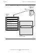
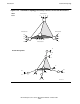
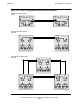
Figure 1-15 illustrates the first step in constructing the tetrahedral topology. That first
step is to complete a triangle of processor enclosures.
For simplicity in Figure 1-15, only the relevant routers are shown. These routers are
the ones on the ServerNet expansion boards (SEBs). The upward-pointing arrows from
the routers are connections to the two internal processors in each processor enclosure.
However, be aware that this connection is through another router, the router that
provides ServerNet links to the internal I/O (refer back to Figure 1-12 and Figure 1-13).
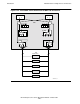
The top part of Figure 1-15 represents the two-processor enclosure, Tetra 8 system
shown in Figure 1-12. Remember that it is possible to connect only two I/O enclosures
to each of the processor enclosures.
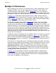
The middle part of Figure 1-15 shows the Tetra 16 version of a two-processor
enclosures system. Note that the I/O capability is increased to ten I/O enclosures.
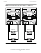
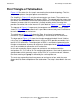
The lower part of Figure 1-15 shows the triangle completed for both X and Y fabrics,
using Tetra 16 topology. The added routers for these SEBs provide connections for a
total of 15 I/O enclosures. The original pair of SEBs is restricted to implementing the
triangle or tetrahedron of processor enclosures (and expansion to ServerNet Clusters),
and is not available for connection to I/O enclosures.
In this and succeeding figures, processor enclosures are numbered with the
designations P/1, P/2, and so on. For configuration purposes, these mostly equate to a
group number, which generally means all the CRUs in a system enclosure; however,
the exact meaning of a group is defined by the service processor.
The next step, expanding from three processor enclosures to four, adds the extra
dimension that allows completion of the tetrahedron. That step is described in the next
topic.