
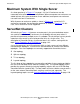
NonStop S-Series Server Description Manual (G06.27+)


Introduction
HP NonStop S-Series Server Description Manual—520331-004
1-38
Modular I/O
Modular I/O
Up to this point, the I/O topologies have considered only configurations that use I/O
enclosures of the same form factor as processor enclosures. One type of enclosure
can be converted to the other type. However, an entirely different I/O topology is also
available that differs significantly from that provided by connection through the
multifunction boards (MFIOBs) in I/O enclosures, that of modular I/O. (For
comparison, refer to Figure 1-10 on page 1-19.) Modular I/O uses different cabinetry
and architecture, and is described here and in the next three topics.
In addition to architectural differences, modular I/O uses different physical packaging.
For example, whereas the I/O enclosure physically stands on the floor or on top of
another enclosure and has its own front and back doors, the equivalent modular I/O
enclosure mounts inside a cabinet that provides standard 19-inch rack mount rails.
That external cabinet, which provides the front and back doors, is much larger than the
I/O enclosures previously described and has a totally different appearance. It can
contain a variable number of modular I/O enclosures.
The primary design intent of modular I/O is to provide extremely high bandwidth
access to a large array of storage and communication devices. Secondarily, modular
I/O provides for increased fault tolerance through fault isolation to smaller module
components and for easy replacement of those components. Module components can
be added online, thus making it possible to expand the I/O system with minimal effort.
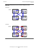
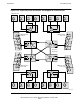
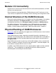
Figure 1-20 illustrates how I/O modules fit into the NonStop server architecture. As
indicated, each module primarily consists of a ServerNet switch and five slots for
ServerNet adapters. The figure assumes that Fibre Channel ServerNet adapters
(FCSAs) are installed in those slots. However, other ServerNet adapters that have the
appropriate form factor, such as Ethernet adapters (G4SA, for example), can be
installed here.
ServerNet switches are always paired between two I/O modules. Although it might
appear that one module is accessed only through the X fabric and the other is
accessed only through the Y fabric, there is actually a cross coupling between the two
modules so that all ten ServerNet adapters in the two modules are accessed through
both X and Y fabrics. This arrangement is primarily for packaging efficiency, and the
cross coupling occurs through backplane connections in the enclosure.
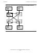
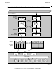
Two 12-port routers are used in each ServerNet switch to enable routing of ServerNet
messages to and from all ten ServerNet adapter slots.
Fibre Channel ServerNet adapters provide two ports for external connection, each
controlled by individual ServerNet addressable controllers (SACs). This feature adds
connection capacity to very large external disk arrays such as the Enterprise Storage
System (ESS).