
NonStop S-Series Server Description Manual (G06.27+)


Introduction
HP NonStop S-Series Server Description Manual—520331-004
1-50
Layered Topologies for 6780 Switches
Layered Topologies for 6780 Switches
ServerNet clusters that use 6780 switches provide more extensive clustering capability
than that of the 6770 switches described in the preceding four topics. Instead of being
configured in a star topology, the 6780 switches are configured in a layered topology,
using one or more switch layers and one or more switch zones. The number of
ServerNet nodes supported depends on the number of switch layers and the number
of switch zones. This topic first considers the single-zone case. Multiple zones are
considered separately in the succeeding topic, Connections Between Zones in Layered
Topology on page 1-52.
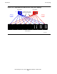
Figure 1-26 illustrates three cases: a single layer, two layers, and four layers. As
shown for the first two cases, each layer in the zone supports up to 8 nodes. (The
nodes are not shown in the four-layer case for illustrative simplicity.) Therefore, with
the maximum number of four layers, 32 nodes is the maximum number of nodes for
one zone.
Each pair of 6780 switches (X and Y) forms one cluster switch layer. The layers are
numbered from one to four, bottom to top.
Keep in mind (as in previous illustrations) that a single server icon is actually a
ServerNet node consisting of a complete multiprocessor server, such as the maximum
example shown in Figure 1-19 on page 1-37.
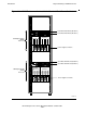
A switch group consists of one to four 6780 switches, and there are distinct X groups
and Y groups. Typically, X groups are physically located in one rack, and Y groups in
another rack.
Note that when two or more layers are present, they are interconnected with layer-to-
layer fiber-optic cables. Each layer is always connected by four cables to each of the
other layers in the group.
In the case of four layers, a tetrahedral arrangement of cables is necessary, so that
each layer can directly access any of the other fours layers. Because this particular
tetrahedron is between layers of switches (rather than between processors), this
arrangement is termed a vertical tetrahedron. Refer to Tetrahedral Topology on
page 1-26 for a general description of tetrahedral configuration.
In the four-layer case of Figure 1-26, the Y switch group is not shown, but is arranged
identically to the X switch group shown.