
NonStop Systems Introduction

NonStop Server Architecture
NonStop Systems Introduction—527825-001
7-7
Low-Latency Routing
a failure occurs that disables one of the pair of SACs or one of the paths, continuous
communication can continue through the other path and SAC.
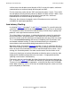
For the second way, notice the four SACs connected to routers 3 and 6. These SACs
are dual-ported, meaning that they connect to both the X fabric and the Y fabric. Dual
porting provides fault tolerance by ensuring that if one path fails, continuous
communication can continue through the other path.
Either way, the existence of two paths to the I/O hardware ensures continuous
availability for input/output operations.
Low-Latency Routing
In reviewing Figure 7-4 on page 7-4 and Figure 7-5 on page 7-6, you will notice that
sometimes a message needs to go through several routers to arrive at its destination.
This requirement means that there must be absolutely minimal delay in getting each
packet of a message from one router to the next.
This minimal delay, or low latency, is achieved by having the router first analyze the
routing information in the packet header. Then, before the rest of the packet even
arrives, the router sends the initial bytes of the packet on their way to the next router.
This is called wormhole routing, and contrasts completely with the common store-
and-forward method of routing. (In store-and-forward routing, the full packet is
accumulated at each router before being forwarded to the next one.)
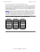
Wormhole routing, illustrated in Figure 7-6 on page 7-8, gets its name from the way a
worm moves through chunks of soil. The worm chews through one chunk of soil and
moves on to the next chunk before its tail has moved through the first chunk. In this
analogy, the ServerNet packet is the worm and the routers are the chunks of soil.
It takes only three bytes of received information to allow the router to select the right
output port for forwarding the packet to the next router. A single packet could be
spanning several routers simultaneously.
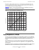
Each router refers to a routing table that helps it determine the correct output port to
use. As shown in Figure 7-6
, the router can connect any input port to any output port.
There are six input ports and six output ports, so that they can be used in full duplex
mode. When necessary, such as in the case of network congestion, routers can store
up to a full packet (or a bit more).