
OSF DCE Application Development Guide--Core Components
OSF DCE Application Development Guide—Core Components
• The DTS daemon is the client.
• The Time-Provider process (TP process) is the server.
Both the RPC-client (DTS daemon) and the server (TP process) must be running on the
same system.
Applications running on RPC communicate through an interface that is well known to
both the client and the server. The RPC interface consists of a set of procedures, data
types, and constants that describe how a client can invoke a routine running on the
server. The server offers the interface to the clients through the Interface Definition
Language (IDL) file.
The IDL file defines the syntax for an operation, including the following:
• The name of the operation
• The data type of the value that the operation returns (if any)
• The order and data types of the operation’s parameters (if any)
The TP process offers two procedures that DTS calls to obtain time values. These
procedures are ContactProvider and ServerRequestProviderTime.
At each system synchronization, DTS makes the initial remote procedure call
(ContactProvider) to a TP process that is assumed to be running on the same node.
If the TP process is active, the RPC call returns the following arguments:
• A successful communication status message
• A control message that DTS uses for further processing
If the TP process is not active, the RPC call either returns a communication status failure
or a time-out occurs. DTS then synchronizes with other servers instead of with the
external time-provider.
If the initial call (ContactProvider) is successful, DTS makes a second call
(ServerRequestProviderTime) to retrieve the timestamps from the external time-
provider. The control message sent by the TP process in the first RPC call specifies the
length of time DTS waits for the RPC call to complete. The TP process returns the
following parameters in the procedure call:
• A communication status message.
• A time structure that contains timestamps collected from the external time-provider.
(DTS then uses these timestamps to complete its synchronization.)
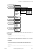
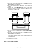
Figure 20-1 illustrates the RPC calling sequence between DTS and the TP process. Note
that solid black lines represent the path followed by input parameters; dashed lines
represent the path followed by output parameters and return values.
The following steps describe the process shown in Figure 20-1:
1. At synchronization time, DTS calls the ContactProvider remote procedure. Input
parameters are passed to the TP client stub, dispatched to the RPC runtime library,
and then passed to the TP server stub.
2. The TP process receives the call and executes the ContactProvider procedure.
20 − 2 Tandem Computers Incorporated 124245