
OSI/MHS Configuration and Management Manual


Configuring Your OSI/MHS Subsystem
OSI/MHS Configuration and Management Manual—424827-003
5-4
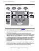
Message Flow
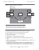
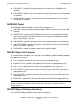
The following text describes the steps shown in Figure 5-2:
1. A UA, a Transfer application or user, or a proprietary system application or user at
MTA1 wants to send a message to a recipient defined as an MS user or a Transfer
application or user on MTA3.
2. The message is submitted by the UA that is represented by APPL object
#JamesJohn in the MTA1 configuration, the message is submitted by the Transfer
application through the Transfer X400 gateway, or the message is submitted by a
proprietary system application using GPI.
3. The routing decision at MTA1 is determined by route-selection criteria specified in
the ROUTE objects defined in the configuration file for MTA1. These criteria,
based on recipient attributes, determine that the MTA object known as #MTA2 is
the destination.
4. MTA2 waits for incoming association requests on the OSI address specified in the
MTA2 MR GROUP objects. An association is established between MTA1 and
MTA2, using the OSI address and attributes defined for MTA object #MTA2 in the
MTA1 configuration. The message is then relayed from MTA1 to MTA2.
Figure 5-2. OSI/MHS Message Flow Example
031VST .VS D
Packet Switch
Ne two rk
Message
Store
Transfer
X400
Gateway
MTA1
Transfer
Application
Message
Store
Transfer
Application
Transfer
X400
Gateway
MTA3
MHS
MTA2
1
12
7
67
2
6
53
45
Re mote
UA
GPI
Local
UA
Local
UA
1
2
1
1
Proprietary
System
Re mote
UA