
OSI/MHS Configuration and Management Manual

Configuring Your OSI/MHS Subsystem
OSI/MHS Configuration and Management Manual—424827-003
5-18
Objects and Attributes
•
Two MR groups share an X.25 normal mode connection; two MR groups share a
LAN connection.
•
Two RS groups share one OSI address to receive association requests from
remote UAs. This is a multigroup configuration.
•
The RS groups share an X.25 normal mode connection.
•
Four MS groups are defined, with mailboxes for users whose access is through the
RS groups.
•
Two adjacent MTAs are defined: MTA1 and MTA2 (there are no other MTAs).
•
Four routes are defined to each adjacent MTA.
•
Backup (alternate) routes are defined.
•
The primary routes go to MTA2 (shown as a solid line in Figure 5-5). The backup
routes go to MTA1 (shown as the dashed line in Figure 5-5).
•
The Transfer X400 gateway is defined.
Objects and Attributes
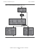
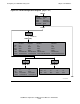
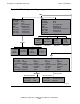
Figure 5-6 shows the OSI/MHS objects and their attributes needed to configure MTA3.
MTA3 has four MR groups and two RS groups. The RS groups share a single OSI
address, and so do each of the two MR groups. This exemplifies the multigroup
feature of OSI/MHS and provides association resilience. If one MR group fails, the
other group receives all the messages that would otherwise have been divided
between the two groups; the same thing happens if an RS group fails.
MTA3 demonstrates using a LAN connection for MR groups. It also is connected to a
Transfer X400 gateway.
The preferred route selection for all messages is through MTA2. Routes configured
through MTA1 are designated as backup routes.