
OSI/MHS Configuration and Management Manual

OSI Address Configuration in OSI/MHS
OSI/MHS Configuration and Management Manual—424827-003
D-8
Address Notation
Thus, there are three groups of SCF addresses—the MR- addresses, the LOC-
addresses and the REM- addresses—that have to be defined both to OSI/MHS and to
the OSI Manager process. Between them they define all six addresses used in an
MTA connection; some of these SCF commands define more than one OSI address
simultaneously.
Address Notation
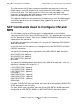
Of the six addresses that are involved in a bidirectional MTA connection the following
paragraphs show how four are configured — IN(S), IN(D), OUT(S) and OUT(D).
Each of these addresses consists of a set of layer addresses corresponding to the
Network, Transport, Session and Presentation layers of the OSI model. The following
examples show only how the Network and Transport layer addresses are configured.
This is generally sufficient to achieve a connection, but if Session or Presentation layer
addresses are required, these can be included in the relevant ADD GROUP #MR or
ADD MTA command.
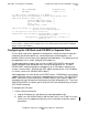
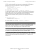
The notation used in the following descriptions is defined in Table D-1.
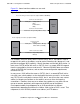
Configuring the Local Addresses
As shown in Figure D-1, the local addresses of the OSI/MHS subsystem consist of the
IN(D) and OUT(S) addresses. (IN(R) is the same as IN(D) ).
IN(D) is defined in the ADD GROUP #MR command together with its associated OSI
stack commands. It defines the address that will be used as the target of incoming
associations to the MR group from adjacent MTAs.
Note. Only five of the six addresses are defined, because OUT(R) is not validated and can
take any value.
Table D-1. Notation Used in Descriptions
OSI Address Network Address Transport Address
IN(S) <in-s-nsap> <in-s-tsel>
IN(D) <in-d-nsap> <in-d-tsel>
OUT(S) <out-s-nsap> <out-s-tsel>
OUT(D) <out-d-nsap> <out-d-tsel>