
OSM User's Guide (G06.27+)
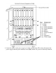
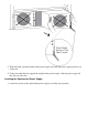
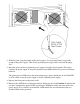
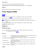
Table Of Contents
- OSM User's Guide
- OSM User's Guide
- What's New in This Guide
- About This Guide
- Related Reading
- Chapter 1. Introducing OSM
- Chapter 2. Preparing the OSM Environment
- Chapter 3. Configuring OSM
- Chapter 4. Starting the OSM Service Connection
- Chapter 5. Using the Management Window
- Chapter 6. Viewing Alarms
- Chapter 7. Viewing Attributes
- Chapter 8. Performing Actions
- Chapter 9. Viewing Summary Reports
- Chapter 10. Managing a System
- Chapter 11. System Resources
- Chapter 12. Managing a ServerNet Cluster
- Chapter 13. Cluster Resources
- Chapter 14. Updating ServerNet Cluster Topology
- Glossary
- Index
- Legal Notice
- Version and Copyright Information
With one hand, grasp the handle of the power supply. Use your other hand to support the
weight of the power supply. Then slowly push the power supply all the way into the empty
slot.
2.
Raise the ejector on the replacement power supply to its fully closed position. This action
connects the power supply to the power interface board (PIB) and the AC power cord directly
behind it.
The green power-on LED above the replacement power supply should now be lit. If the LED
is not lit, either reseat the power supply or install a different power supply.
3.
Replace the front panel on the power shelf.4.
Return to the OSM Service Connection Actions dialog box and click Continue to indicate that
you have completed the physical CRU replacement. OSM then verifies the status of the new
power supply. If it is found to be functional, OSM enables the associated battery that was
disabled earlier in the procedure.
5.