installation and getting started guide hp procurve series 2300 and 2500 switches www.hp.
2353-ed2.
2353-ed2.book Page ii Friday, February 9, 2001 6:00 PM © Copyright 2000, 2001 Hewlett-Packard Company All Rights Reserved. This document contains information which is protected by copyright. Reproduction, adaptation, or translation without prior permission is prohibited, except as allowed under the copyright laws.
2353-ed2.book Page iii Friday, February 9, 2001 6:00 PM Contents 1 Introducing the HP ProCurve Series 2300 and 2500 Switches Front of the Switches . . . . . . . . . . . . . . . . . . . . . . . . . . . . . . . . . . . . . . . . . . 1-2 Network Ports . . . . . . . . . . . . . . . . . . . . . . . . . . . . . . . . . . . . . . . . . . . . . . 1-2 LEDs . . . . . . . . . . . . . . . . . . . . . . . . . . . . . . . . . . . . . . . . . . . . . . . . . . . . . . 1-3 Mode LED Select Button and Indicator LEDs . . . .
2353-ed2.book Page iv Friday, February 9, 2001 6:00 PM 5. Connect the Switch to a Power Source . . . . . . . . . . . . . . . . . . . . . . 2-13 6. Connect the Network Cables . . . . . . . . . . . . . . . . . . . . . . . . . . . . . . . 2-14 Using the RJ-45 Connectors (10/100Base-TX ports) . . . . . . . . . . 2-14 Connecting Cables to the Transceivers . . . . . . . . . . . . . . . . . . . . . 2-14 7. (Optional) Connect a Console to the Switch 2500 . . . . . . . . . . . . . 2-15 Terminal Configuration . . .
2353-ed2.book Page v Friday, February 9, 2001 6:00 PM Downloading New Code (Series 2300 switches only) . . . . . . . . . . . . . . . . . . . . . . . . . . . . . . . . . . 3-12 To Perform the Download: . . . . . . . . . . . . . . . . . . . . . . . . . . . . . . . 3-12 HP Customer Support Services . . . . . . . . . . . . . . . . . . . . . . . . . . . . . . . . 3-13 Before Calling Support . . . . . . . . . . . . . . . . . . . . . . . . . . . . . . . . . . . . . . 3-13 A Specifications Physical . . . . . . .
2353-ed2.
2353-ed2.book Page 1 Friday, February 9, 2001 6:00 PM 1 The HP ProCurve Series 2300 and 2500 Switches are multiport high-speed switches that can be used to build high-performance switched workgroup networks. These switches are store-and-forward devices that offer low latency for high-speed networking.
2353-ed2.
2353-ed2.book Page 3 Friday, February 9, 2001 6:00 PM Introducing the HP ProCurve Series 2300 and 2500 Switches Front of the Switches Table 1-1. Switch LEDs Switch LEDs State Meaning Power (green) On The switch is receiving power. Off The switch is NOT receiving power. Fault (orange) Off Self Test (green) Mode Select (3 green LEDs) Blinking The normal state; indicates that there are no fault conditions on the switch.
2353-ed2.book Page 4 Friday, February 9, 2001 6:00 PM Introducing the HP ProCurve Series 2300 and 2500 Switches Front of the Switches Introducing the HP ProCurve Series 2300 and 2500 Table 1-2. Switch and Transceiver Port LEDs Port LEDs State Meaning Link On Indicates the port is enabled and receiving a link indication from the connected device.
2353-ed2.book Page 5 Friday, February 9, 2001 6:00 PM Introducing the HP ProCurve Series 2300 and 2500 Switches Front of the Switches To optimize the amount of information that can be displayed for each of the switch ports without overwhelming you with LEDs, the Series 2300 and 2500 switches use a Mode LED for each port. The operation of this LED is controlled by the Mode LED Select button, and the current setting is indicated by the Mode LED Select indicator LEDs near the button.
2353-ed2.book Page 6 Friday, February 9, 2001 6:00 PM Introducing the HP ProCurve Series 2300 and 2500 Switches Front of the Switches Introducing the HP ProCurve Series 2300 and 2500 Console Port (Series 2500 Switches only) This port is available on the Series 2500 switches, and is used to connect a console to the switch by using the serial cable supplied with the switch. This connection is described under “Connect a Console to the Switch” in chapter 2, “Installing the Switches”.
2353-ed2.book Page 7 Friday, February 9, 2001 6:00 PM Introducing the HP ProCurve Series 2300 and 2500 Switches Back of the Switches This button is used for these purposes: ■ Deleting Passwords - When pressed by itself for at least one second, the button deletes any switch console access passwords that you may have configured. Use this feature if you have misplaced the password and need console access.
2353-ed2.book Page 8 Friday, February 9, 2001 6:00 PM Introducing the HP ProCurve Series 2300 and 2500 Introducing the HP ProCurve Series 2300 and 2500 Switches Switch Features Switch Features The features of the Series 2300 and 2500 switches include: ■ 12 or 24 autosensing 10/100Base-TX RJ-45 ports with Auto MDI/MDI-X. ■ two slots for installing supported gigabit or 100Base-FX transceivers.
2353-ed2.book Page 9 Friday, February 9, 2001 6:00 PM Introducing the HP ProCurve Series 2300 and 2500 Switches Switch Operation Overview support for up to 30 IEEE 802.1Q-compliant VLANs so you can divide the attached end nodes into logical groupings that fit your business needs. ■ support for many advanced features to enhance network performance and network traffic control—described in the Management and Configuration Guide that came with your Series 2500 switch.
2353-ed2.book Page 10 Friday, February 9, 2001 6:00 PM Introducing the HP ProCurve Series 2300 and 2500 Switches Switch Operation Overview Introducing the HP ProCurve Series 2300 and 2500 Network Moves and Changes. When a PC, server, printer, or other network device is moved in the network, and becomes connected to a different switch port, the Series 2300 and 2500 switches automatically recognize the change and update their address table with the new port location of the device.
2353-ed2.book Page 1 Friday, February 9, 2001 6:00 PM 2 Installing the Series 2300 and 2500 Switches The HP Series 2300 and 2500 switches are easy to install. They each come with an accessory kit that includes the brackets for mounting the switch in a standard 19-inch telco rack, in an equipment cabinet, or on a wall, and with rubber feet that can be attached so the switch can be securely located on a horizontal surface.
2353-ed2.book Page 2 Friday, February 9, 2001 6:00 PM Installing the Series 2300 and 2500 Switches Installation Procedures Installation Procedures Summary Installing the Series 2300 and 2500 Switches Follow these easy steps to install your switch. The rest of this chapter provides details on these steps. 1. Prepare the installation site (page 2-4).
2353-ed2.book Page 3 Friday, February 9, 2001 6:00 PM Installing the Series 2300 and 2500 Switches Installation Procedures Installation Precautions: Follow these precautions when installing your HP Series 2300 and 2500 switches. Warning ■ The rack or cabinet should be adequately secured to prevent it from becoming unstable and/or falling over.
2353-ed2.book Page 4 Friday, February 9, 2001 6:00 PM Installing the Series 2300 and 2500 Switches Installation Procedures 1. Prepare the Installation Site ■ Cabling Infrastructure - Ensure that the cabling infrastructure meets the necessary network specifications. See the following table for cable types and lengths, and see appendix B, “Cables and Connectors” for more information: Table 2-1.
53-ed2.book Page 5 Friday, February 9, 2001 6:00 PM Installing the Series 2300 and 2500 Switches Installation Procedures Port Type Cable Type Length Limits Fiber Optic Cables 62.5/125 µm or 50/125 µm core/cladding diameter, graded-index, multimode fiber-optic cables that are fitted with SC connectors • 2 kilometers for full-duplex connections Gigabit-SX (on the Gigabit-SX transceivers) 62.
2353-ed2.book Page 6 Friday, February 9, 2001 6:00 PM Installing the Series 2300 and 2500 Switches Installation Procedures 2. Install Transceivers (optional) Install a transceiver into one or both of the slots as shown in the illustration below. For installation details, see the instructions in the Installation Guide that comes with the transceiver. The slot cover can be removed with either a flat-bladed or Torx T-10 screwdriver. Keep the slot cover for future use.
2353-ed2.book Page 7 Friday, February 9, 2001 6:00 PM Installing the Series 2300 and 2500 Switches Installation Procedures Installing a Transceiver in the Switch 1. Insert transceiver into the guides and slide it in until it stops. 2. Press in firmly until the transceiver is flush with the face of the switch. 3. Tighten the retaining screws on the transceiver until they secure, but do not overtighten them. 4. Press the Reset button to reset/reboot the switch and initialize the transceivers.
2353-ed2.book Page 8 Friday, February 9, 2001 6:00 PM Installing the Series 2300 and 2500 Switches Installation Procedures 2. Check the LEDs on the switch as described below.
2353-ed2.book Page 9 Friday, February 9, 2001 6:00 PM Installing the Series 2300 and 2500 Switches Installation Procedures 4. Mount the Switch After you have verified that the switch passes self test, you are ready to mount the switch in a stable location.
2353-ed2.book Page 10 Friday, February 9, 2001 6:00 PM Installing the Series 2300 and 2500 Switches Installation Procedures Note Steps 2, 3, and 4 below describe a convenient method of mounting the switch in a rack by placing it on two screws that you first install in the rack. You may, instead, just hold the switch with attached brackets up to the rack and move it vertically until rack holes line up with the bracket notches, then insert and tighten the four screws holding the brackets to the rack. 2.
2353-ed2.book Page 11 Friday, February 9, 2001 6:00 PM Installing the Series 2300 and 2500 Switches Installation Procedures 3. Place the switch in the rack and lower it so the notches in the bottom of the bracket slide onto the screws, then tighten these screws. 4. Install the other number 12-24 screw through the hole in each bracket. Tighten these screws. .
2353-ed2.book Page 12 Friday, February 9, 2001 6:00 PM Installing the Series 2300 and 2500 Switches Installation Procedures Horizontal Surface Mounting Place the switch on a table or other horizontal surface. The switch comes with rubber feet in the accessory kit that can be used to help keep the switch from sliding on the surface. Attach the rubber feet to the four corners on the bottom of the switch within the embossed angled lines. Use a sturdy surface in an uncluttered area.
2353-ed2.book Page 13 Friday, February 9, 2001 6:00 PM Installing the Series 2300 and 2500 Switches Installation Procedures 2. Attach the switch to the wall or wood surface with two 5/8-inch number 12 wood screws (not included). For “Bookshelf” Wall Mounting For “Flat” Wall Mounting 5/8-inch wood screw 5/8-inch wood screws Installing the Series 2300 and 2500 Switches second 5/8-inch wood screw (hidden) 5. Connect the Switch to a Power Source 1.
2353-ed2.book Page 14 Friday, February 9, 2001 6:00 PM Installing the Series 2300 and 2500 Switches Installation Procedures 6. Connect the Network Cables Connect the network cables, described under “Cabling Infrastructure” (page 2-4), from the network devices or your patch panels to the fixed RJ-45 ports on the switch or the ports on any transceivers you have installed in the switch.
2353-ed2.book Page 15 Friday, February 9, 2001 6:00 PM Installing the Series 2300 and 2500 Switches Installation Procedures 7.
2353-ed2.book Page 16 Friday, February 9, 2001 6:00 PM Installing the Series 2300 and 2500 Switches Installation Procedures If you want to operate the console using a different configuration, make sure you change the settings on both the terminal and on the switch so they are compatible. Change the switch settings first, then change the terminal settings, then reboot the switch and reestablish the console session.
2353-ed2.book Page 17 Friday, February 9, 2001 6:00 PM Installing the Series 2300 and 2500 Switches Getting Started With Switch Configuration (Series 2500 Switches Only) Getting Started With Switch Configuration (Series 2500 Switches Only) This section is a guide for using the console Switch Setup screen to quickly assign an IP (Internet Protocol) address and subnet mask to the switch, set a Manager password, and, optionally, configure other basic features.
2353-ed2.book Page 18 Friday, February 9, 2001 6:00 PM Installing the Series 2300 and 2500 Switches Getting Started With Switch Configuration (Series 2500 Switches Only) Using the Console Setup Screen The quickest and easiest way to minimally configure the switch for management and password protection in your network is to use a direct console connection to the switch, start a console session, and access the Switch Setup screen. 1.
2353-ed2.book Page 19 Friday, February 9, 2001 6:00 PM Installing the Series 2300 and 2500 Switches Getting Started With Switch Configuration (Series 2500 Switches Only) Here is some information on the fields in the Setup screen.
2353-ed2.book Page 20 Friday, February 9, 2001 6:00 PM Installing the Series 2300 and 2500 Switches Using the IP Address for Remote Switch Management (Series 2500 Switches Only) Where to Go From Here The above procedure configures your switch with a Manager password, IP address, and subnet mask. With the proper network connections, you can now manage the switch from a PC equipped with Telnet and/or a web browser or from an SNMP network management station.
2353-ed2.book Page 21 Friday, February 9, 2001 6:00 PM Installing the Series 2300 and 2500 Switches Using the IP Address for Remote Switch Management (Series 2500 Switches Only) Starting a Web Browser Session Your Series 2500 switch can be managed through a graphical interface that you can access from any PC or workstation on the network by running your web browser and typing in the switch’s IP address as the URL.
2353-ed2.book Page 22 Friday, February 9, 2001 6:00 PM Installing the Series 2300 and 2500 Switches Sample Network Topologies Sample Network Topologies This section shows you a few sample network topologies in which the Series 2300 and 2500 switches are implemented. For more topology information, see the HP network products World Wide Web site, http://www.hp.com/go/hpprocurve.
2353-ed2.book Page 23 Friday, February 9, 2001 6:00 PM Installing the Series 2300 and 2500 Switches Sample Network Topologies As a Segment Switch Server with “Gigabit” Ethernet NIC category 5 twisted-pair “straight-through” or “crossover” cable for 1000 Mbps connection to server Switch 2512 Gigabit fiber-optic cable to backbone PCs, printers, and local servers twisted-pair “straight-through” cables to end nodes The Series 2300 and 2500 switches also work well as segment switches.
2353-ed2.book Page 24 Friday, February 9, 2001 6:00 PM Installing the Series 2300 and 2500 Switches Sample Network Topologies Connecting to a Backbone Switch Switch 2524 Installing the Series 2300 and 2500 Switches to Gigabit-Ethernet backbone Switch 8000M Gigabit fiber-optic cable Switch 2512 The simpler desktop and segment networks shown in the previous two examples can easily be combined and expanded.
2353-ed2.book Page 25 Friday, February 9, 2001 6:00 PM Installing the Series 2300 and 2500 Switches Sample Network Topologies Stacking the Switches (Series 2500 only) The Series 2500 switches can be connected together, through standard network connections, and managed through a single IP address. Up to 16 switches can be connected together in such a “virtual stack”. You identify one of the switches as the “Commander” and give that switch an IP address.
2353-ed2.
2353-ed2.book Page 1 Friday, February 9, 2001 6:00 PM 3 Troubleshooting This chapter describes how to troubleshoot your HP ProCurve Series 2300 and 2500 switches. Note that this document describes troubleshooting mostly from a hardware perspective.
2353-ed2.book Page 2 Friday, February 9, 2001 6:00 PM Troubleshooting Basic Troubleshooting Tips ■ Improper Network Topologies. It is important to make sure you have a valid network topology. Common topology faults include excessive cable length and excessive repeater delays between end nodes. If you have network problems after recent changes to the network, change back to the previous topology. If you no longer experience the problems, the new topology is probably at fault.
2353-ed2.book Page 3 Friday, February 9, 2001 6:00 PM Troubleshooting Basic Troubleshooting Tips Make sure that all devices connected to the Series 2300 and 2500 switches are configured to auto negotiate, or are configured to connect at half duplex (all hubs are configured this way, for example). ■ Check the port configuration (Series 2500 Switches only).
2353-ed2.book Page 4 Friday, February 9, 2001 6:00 PM Troubleshooting Diagnosing with the LEDs Diagnosing with the LEDs Tables 3-1 shows LED patterns on the switch and the switch modules that indicate problem conditions. 1. Check in the table for the LED pattern that you see on your switch. 2. Refer to the corresponding diagnostic tip on the next few pages. Table 3-1.
2353-ed2.book Page 5 Friday, February 9, 2001 6:00 PM Troubleshooting Diagnosing with the LEDs Diagnostic Tips: Problem Solution ➊ The switch is not plugged into an active AC power source, or the switch’s power supply may have failed. 1. Verify that the power cord is plugged into an active power source and to the switch. Make sure these connections are snug. 2. Try power cycling the switch by unplugging and plugging the power cord back in. 3.
2353-ed2.book Page 6 Friday, February 9, 2001 6:00 PM Troubleshooting Troubleshooting Diagnosing with the LEDs Tip Problem Solution ➏ The network connection is not working properly. Try the following procedures: • For the indicated port, verify that both ends of the cabling, at the switch and the connected device, are connected properly. • Verify the connected device and switch are both powered on and operating correctly.
2353-ed2.book Page 7 Friday, February 9, 2001 6:00 PM Troubleshooting Diagnosing with the LEDs Tip Problem Solution ➑ A transceiver was installed and the switch has not yet been reset. When you install transceivers in the transceiver slots, you must reset or reboot the switch so the switch processor can properly initialize and configure the transceiver. The flashing LED informs you that the transceiver is not initialized. The transceiver will not work properly until the switch is reset or rebooted.
2353-ed2.
2353-ed2.book Page 9 Friday, February 9, 2001 6:00 PM Troubleshooting Hardware Diagnostic Tests Hardware Diagnostic Tests Testing the Switch by Resetting It If you believe that the switch is not operating correctly, you can reset the switch to test its circuitry and operating code.
2353-ed2.book Page 10 Friday, February 9, 2001 6:00 PM Troubleshooting Hardware Diagnostic Tests Testing Twisted-Pair Cabling Network cables that fail to provide a link or provide an unreliable link between the switch and the connected network device may not be compatible with the IEEE 802.3 Type 10Base-T, 100Base-TX, or 1000Base-T standards. The twisted-pair cables attached to the Series 2300 and 2500 switches must be compatible with the appropriate standards.
2353-ed2.book Page 11 Friday, February 9, 2001 6:00 PM Troubleshooting Restoring the Factory Default Configuration (Series 2500 switches only) Restoring the Factory Default Configuration (Series 2500 switches only) As part of your troubleshooting process on the Series 2500 switches, it may become necessary to return the switch configuration to the factory default settings.
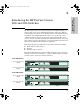
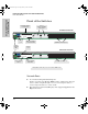
2353-ed2.book Page 12 Friday, February 9, 2001 6:00 PM Troubleshooting Downloading New Code (Series 2300 switches only) Downloading New Code (Series 2300 switches only) If product enhancements occur for the Series 2300 switches, even though they are unmanaged devices, it is possible to download new code to the switch through the Download Port on the front of the switch. The new code would be available on the HP ProCurve web site, http://www.hp.com/go/hpprocurve.
2353-ed2.book Page 13 Friday, February 9, 2001 6:00 PM Troubleshooting HP Customer Support Services HP Customer Support Services If you are still having trouble with your switch, Hewlett-Packard offers support 24 hours a day, seven days a week through the use of a number of automated electronic services. See the Customer Support/Warranty booklet that came with your switch for information on how to use these services to get technical support. The HP ProCurve web site, http://www.hp.
2353-ed2.
2353-ed2.book Page 1 Friday, February 9, 2001 6:00 PM A Specifications The following specifications apply to both the Series 2300 and 2500 switches. Physical Width: 44.2 cm (17.4 in) Depth: 20.5 cm (8.1 in) Height: 4.4 cm (1.7 in) Weight: 2.8 kg (6.2 lbs) Electrical The switches automatically adjust to any voltage between 100-127 and 200-240 volts and either 50 or 60 Hz. AC voltage: 100–127 volts 200–240 volts Maximum current: 2.4 A 1.
2353-ed2.book Page 2 Friday, February 9, 2001 6:00 PM Specifications Acoustic Geraeuschemission LwA=54 dB am fiktiven Arbeitsplatz nach DIN 45635 T.19 Noise Emission LwA=54 dB at virtual workspace according to DIN 45635 T.19 Connectors ■ The 10/100 Mbps RJ-45 twisted-pair ports are compatible with the IEEE 802.3u 100Base-TX and IEEE 802.3 Type 10Base-T standards. ■ The 1000 Mbps RJ-45 twisted-pair port on the 100/1000-T transceiver is compatible with the IEEE 802.3ab standard.
2353-ed2.book Page 1 Friday, February 9, 2001 6:00 PM B Switch Ports and Network Cables Switch Ports and Network Cables This appendix includes switch connector information and network cable information for cables that should be used with the Series 2300 and 2500 switches, including minimum pin-out information and specifications for twisted-pair cables. Note Incorrectly wired cabling is the most common cause of problems for LAN communications.
2353-ed2.book Page 2 Friday, February 9, 2001 6:00 PM Switch Ports and Network Cables Switch Ports and Network Cables Cables Twisted-Pair 10 Mbps Operation Category 3, 4, or 5 100-ohm unshielded twisted-pair (UTP) or shielded twisted-pair (STP) cable, complying with IEEE 802.3 Type 10Base-T specifications, fitted with RJ-45 connectors 100 Mbps Operation Category 5 100-ohm UTP or STP cable, complying with IEEE 802.
2353-ed2.book Page 3 Friday, February 9, 2001 6:00 PM Switch Ports and Network Cables Twisted-Pair Cable/Connector Pin-Outs Fiber-Optic 62.5/125 µm or 50/125 µm (core/cladding) diameter, gradedindex, multimode fiber-optic cables, complying with the ITU-T G.651 and ISO/IEC 793-2 Type A1b or A1a respectively, fitted with MT-RJ connectors Gigabit-SX 62.5/125 µm or 50/125 µm (core/cladding) diameter, gradedindex, multimode fiber-optic cables, complying with the ITU-T G.
2353-ed2.book Page 4 Friday, February 9, 2001 6:00 PM Switch Ports and Network Cables Twisted-Pair Cable/Connector Pin-Outs Switch Ports and Network Cables If you happen to use a correctly wired crossover cable, though, the switch will still be able to automatically detect the MDI/MDI-X operation and link correctly to the connected device.
2353-ed2.book Page 5 Friday, February 9, 2001 6:00 PM Switch Ports and Network Cables Twisted-Pair Cable/Connector Pin-Outs Because of the HP Auto-MDIX operation of the 10/100 ports on the switches, for all network connections, to PCs, servers or other end nodes, or to hubs or other switches, you can use “straight-through” cables.
2353-ed2.book Page 6 Friday, February 9, 2001 6:00 PM Switch Ports and Network Cables Twisted-Pair Cable/Connector Pin-Outs Switch Ports and Network Cables Crossover Twisted-Pair Cable for 10 Mbps or 100 Mbps Network Connection The HP Auto-MDIX operation of the 10/100 ports on the switches also allows you to use “crossover” cables for all network connections, to PCs, servers or other end nodes, or to hubs or other switches.
2353-ed2.book Page 7 Friday, February 9, 2001 6:00 PM Switch Ports and Network Cables Twisted-Pair Cable/Connector Pin-Outs 1000Base-T connections require that all four pairs or wires be connected. Cable Diagram Note Pins 1 and 2 on connector “A” must be wired as a twisted pair to pins 1 and 2 on connector “B”. Pins 3 and 6 on connector “A” must be wired as a twisted pair to pins 3 and 6 on connector “B”. Pins 4 and 5 on connector “A” must be wired as a twisted pair to pins 4 and 5 on connector “B”.
2353-ed2.
2353-ed2.book Page 1 Friday, February 9, 2001 6:00 PM C Safety and EMC Regulatory Statements Safety Information WARNING A WARNING in the manual denotes a hazard that can cause injury or death. CAUTION A CAUTION in the manual denotes a hazard that can damage equipment. Safety and EMC Regulatory Statements ! Documentation reference symbol. If the product is marked with this symbol, refer to the product documentation to get more information about the product.
2353-ed2.book Page 2 Friday, February 9, 2001 6:00 PM Safety and EMC Regulatory Statements Informations concernant la sécurité Informations concernant la sécurité Safety and EMC Regulatory Statements ! Symbole de référence à la documentation. Si le produit est marqué de ce symbole, reportez-vous à la documentation du produit afin d'obtenir des informations plus détaillées. WARNING Dans la documentation, un WARNING indique un danger susceptible d'entraîner des dommages corporels ou la mort.
2353-ed2.book Page 3 Friday, February 9, 2001 6:00 PM Safety and EMC Regulatory Statements Hinweise zur Sicherheit Hinweise zur Sicherheit ! Symbol für Dokumentationsverweis. Wenn das Produkt mit diesem Symbol markiert ist, schlagen Sie bitte in der Produktdokumentation nach, um mehr Informationen über das Produkt zu erhalten. WARNING Eine WARNING in der Dokumentation symbolisiert eine Gefahr, die Verletzungen oder sogar Todesfälle verursachen kann.
2353-ed2.book Page 4 Friday, February 9, 2001 6:00 PM Safety and EMC Regulatory Statements Considerazioni sulla sicurezza Considerazioni sulla sicurezza Safety and EMC Regulatory Statements ! Simbolo di riferimento alla documentazione. Se il prodotto è contrassegnato da questo simbolo, fare riferimento alla documentazione sul prodotto per ulteriori informazioni su di esso. WARNING La dicitura WARNINGdenota un pericolo che può causare lesioni o morte.
2353-ed2.book Page 5 Friday, February 9, 2001 6:00 PM Safety and EMC Regulatory Statements Consideraciones sobre seguridad Consideraciones sobre seguridad ! Símbolo de referencia a la documentación. Si el producto va marcado con este símbolo, consultar la documentación del producto a fin de obtener mayor información sobre el producto. WARNING Una WARNING en la documentación señala un riesgo que podría resultar en lesiones o la muerte.
2353-ed2.
2353-ed2.
2353-ed2.book Page 8 Friday, February 9, 2001 6:00 PM Safety and EMC Regulatory Statements EMC Regulatory Statements EMC Regulatory Statements U.S.A. FCC Class A Safety and EMC Regulatory Statements This equipment has been tested and found to comply with the limits for a Class A digital device, pursuant to Part 15 of the FCC Rules. These limits are designed to provide reasonable protection against interference when the equipment is operated in a commercial environment.
2353-ed2.
2353-ed2.
2353-ed2.
Index 2353-ed2.
2353-ed2.
2353-ed2.
2353-ed2.
2353-ed2.
Technical information in this document is subject to change without notice. ©Copyright Hewlett-Packard Company 2000, 2001. All right reserved. Reproduction, adaptation, or translation without prior written permission is prohibited except as allowed under the copyright laws.