
RDF System Management Manual
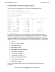
Table Of Contents
- RDF System Management Manual
- What’s New in This Manual
- About This Manual
- 1 Introducing RDF
- RDF Subsystem Overview
- RDF Processes
- RDF Operations
- Reciprocal and Chain Replication
- Available Types of Replication to Multiple Backup Systems
- Triple Contingency
- Loopback Configuration (Single System)
- Online Product Initialization
- Online Database Synchronization
- Online Dumps
- Subvolume- and File-Level Replication
- Shared Access DDL Operations
- EMS Support
- SMF Support
- RTD Warning Thresholds
- Process-Lockstep Operation
- Support for Network Transactions
- RDF and NonStop SQL/MX
- Zero Lost Transactions (ZLT)
- Monitoring RDF Entities With ASAP
- 2 Preparing the RDF Environment
- 3 Installing and Configuring RDF
- 4 Operating and Monitoring RDF
- 5 Managing RDF
- Recovering From File System Errors
- Handling Disk Space Problems
- Responding to Operational Failures
- Stopping RDF
- Restarting RDF
- Carrying Out a Planned Switchover
- Takeover Operations
- Reading the Backup Database
- Access to Backup Databases in a Consistent State
- RDF and NonStop SQL/MP DDL Operations
- RDF and NonStop SQL/MX Operations
- Backing Up Image Trail Files
- Making Online Dumps With Updaters Running
- Doing FUP RELOAD Operations With Updaters Running
- Exception File Optimization
- Switching Disks on Updater UPDATEVOLUMES
- 6 Maintaining the Databases
- 7 Online Database Synchronization
- 8 Entering RDFCOM Commands
- 9 Entering RDFSCAN Commands
- 10 Triple Contingency
- 11 Subvolume- and File-Level Replication
- 12 Auxiliary Audit Trails
- 13 Network Transactions
- Configuration Changes
- RDF Network Control Files
- Normal RDF Processing Within a Network Environment
- RDF Takeovers Within a Network Environment
- Takeover Phase 1 – Local Undo
- Takeover Phase 2 – File Undo
- Takeover Phase 3 – Network Undo
- Takeover Phase 3 Performance
- Communication Failures During Phase 3 Takeover Processing
- Takeover Delays and Purger Restarts
- Takeover Restartability
- Takeover and File Recovery
- The Effects of Undoing Network Transactions
- Takeover and the RETAINCOUNT Value
- Network Configurations and Shared Access NonStop SQL/MP DDL Operations
- Network Validation and Considerations
- RDF Re-Initialization in a Network Environment
- RDF Networks and ABORT or STOP RDF Operations
- RDF Networks and Stop-Update-to-Time Operations
- Sample Configurations
- RDFCOM STATUS Display
- 14 Process-Lockstep Operation
- Starting a Lockstep Operation
- The DoLockstep Procedure
- The Lockstep Transaction
- RDF Lockstep File
- Multiple Concurrent Lockstep Operations
- The Lockstep Gateway Process
- Disabling Lockstep
- Reenabling Lockstep
- Lockstep Performance Ramifications
- Lockstep and Auxiliary Audit Trails
- Lockstep and Network Transactions
- Lockstep Operation Event Messages
- 15 NonStop SQL/MX and RDF
- Including and Excluding SQL/MX Objects
- Obtaining ANSI Object Names From Updater Event Messages
- Creating NonStop SQL/MX Primary and Backup Databases from Scratch
- Creating a NonStop SQL/MX Backup Database From an Existing Primary Database
- Online Database Synchronization With NonStop SQL/MX Objects
- Offline Synchronization for a Single Partition
- Online Synchronization for a Single Partition
- Correcting Incorrect NonStop SQL/MX Name Mapping
- Consideration for Creating Backup Tables
- Restoring to a Specific Location
- Comparing NonStop SQL/MX Tables
- 16 Zero Lost Transactions (ZLT)
- A RDF Command Summary
- B Additional Reference Information
- C Messages
- D Operational Limits
- E Using ASAP
- Index
Entering RDFCOM Commands
HP NonStop RDF System Management Manual—524388-003
8-96
Command Overview
For extractors, receivers, and image trails, the configured ATINDEX value is displayed
in parentheses following the object name. In the above example, the extractor $RE00
and receiver $RR00 are associated with the MAT, while the extractor $RE01 and
receiver $RR01 are associated with auxiliary audit trail AUX01.
Because of insufficient space, however, ATINDEX values could not be displayed
explicitly for updaters. To determine the ATINDEX value of a particular updater, see the
ATINDEX value of the associated secondary image trail.
In this example, a monitor process and two extractor processes are configured on the
primary system, and two receiver processes and three updater processes are
configured on the backup system. For each process, the following items appear,
indicated by column headings near the top of the display:
RDF Process
The first column of the display identifies the type of process. Notice that each updater
process is identified by the names of both the primary volume the updater process is
protecting and the corresponding volume on the backup system. In this example, each
volume being updated on the backup system has the same name as the corresponding
volume on the primary system (for example, updates to the volume $DATA07 on the
primary system are duplicated by the updater process $RU02 to the volume $DATA07
on the backup system).
Name
The second column specifies the name of each process.
RTD Time
The third column (labeled RTD Time) specifies the current RDF time delay (RTD) value
for the extractor process, receiver process, and all updater processes. These values
can help you determine how far behind the application program each process is
running.
On the primary system, TMF attaches a timestamp to every commit and abort status
record generated for the application program. The extractor process, in turn, attaches
the most recent TMF commit/abort timestamp to all data modification image records.
The RTD value for each extractor is the difference between the “last modified time” of
the TMF master audit trail (MAT) and the timestamp in the most recent image record
processed by that extractor.
As each receiver processes records, it writes them to a buffer and then moves them
from the buffer as the need arises. Each receiver keeps track of the last audit record it
wrote to disk at the last save point; if the receiver must restart because the primary
system goes down, this save point becomes the receiver’s restart point. The RTD for a
receiver is the difference between the “last modified time” of the TMF MAT and the
timestamp that identifies the associated restart point.