SCSI Extender Installation and User’s Guide Abstract This guide describes how to install and operate SCSI extenders. Product Version N.A. Supported Release Version Updates (RVUs) This guide supports G06.22 and all subsequent G-series RVUs until otherwise indicated in a new edition.
Document History Part Number Product Version 522347-002 N.A.
SCSI Extender Installation and User’s Guide Index Figures What’s New in This Manual iii Manual Information iii New and Changed Information About This Manual v Notation Conventions Tables iii v 1. SCSI Extender Overview SCSI Extender Configuration SCSI Extender 1-4 Fibre Channel Port 1-5 SCSI Port 1-5 SCSI IDs 1-6 1-2 2. Installing a SCSI Extender Enclosure SCSI Extender Enclosure 2-2 Installing a SCSI Extender Enclosure 2-3 Supported Stacking Configurations 2-3 3.
5. Subsystem Control Facility (SCF) Configuration Contents Power On the SCSI-to-Fiber extender (CTSFE) 4-4 5. Subsystem Control Facility (SCF) Configuration Configure the SCSI Extenders 5-1 Configure the Storage Devices 5-2 6. Operating and Troubleshooting the SCSI Extender TSM and OSM 6-1 Visual Inspection 6-1 Technical Support 6-2 LED Status Lights 6-2 Index Figures Figure 1-1. Figure 1-2. Figure 1-3. Figure 2-1. Figure 2-2. Figure 2-3. Figure 2-4. Figure 2-5. Figure 4-1. Figure 4-2. Figure 6-1.
What’s New in This Manual Manual Information SCSI Extender Installation and User’s Guide Abstract This guide describes how to install and operate SCSI extenders. Product Version N.A. Supported Release Version Updates (RVUs) This guide supports G06.22 and all subsequent G-series RVUs until otherwise indicated in a new edition. Part Number Published 522347-002 December 2003 Document History Part Number Product Version Published 522347-002 N.A.
What’s New in This Manual New and Changed Information SCSI Extender Installation and User’s Guide— 522347-002 iv
About This Manual Notation Conventions Hypertext Links Blue underline is used to indicate a hypertext link within text. By clicking a passage of text with a blue underline, you are taken to the location described. For example: This requirement is described under Backup DAM Volumes and Physical Disk Drives on page 3-2. General Syntax Notation This list summarizes the notation conventions for syntax presentation in this manual. UPPERCASE LETTERS. Uppercase letters indicate keywords and reserved words.
General Syntax Notation About This Manual each side of the list, or horizontally, enclosed in a pair of brackets and separated by vertical lines. For example: FC [ num ] [ -num ] [ text ] K [ X | D ] address { } Braces. A group of items enclosed in braces is a list from which you are required to choose one item. The items in the list can be arranged either vertically, with aligned braces on each side of the list, or horizontally, enclosed in a pair of braces and separated by vertical lines.
Notation for Messages About This Manual Line Spacing. If the syntax of a command is too long to fit on a single line, each continuation line is indented three spaces and is separated from the preceding line by a blank line. This spacing distinguishes items in a continuation line from items in a vertical list of selections.
Change Bar Notation About This Manual either vertically, with aligned braces on each side of the list, or horizontally, enclosed in a pair of braces and separated by vertical lines. For example: obj-type obj-name state changed to state, caused by { Object | Operator | Service } process-name State changed from old-objstate to objstate { Operator Request. } { Unknown. } | Vertical Line. A vertical line separates alternatives in a horizontal list that is enclosed in brackets or braces.
1 SCSI Extender Overview SCSI Extender Configuration SCSI Extender 1-4 Fibre Channel Port 1-5 SCSI Port 1-5 SCSI IDs 1-6 1-2 SCSI Extender Installation and User’s Guide— 522347-002 1 -1
SCSI Extender Configuration SCSI Extender Overview SCSI Extender Configuration The SCSI Extender is a fast, reliable data transport system that allows simultaneous communications between HP NonStop S-Series servers and the supported storage devices listed in Table 1-1. Table 1-1. Supported Storage Devices Release Version Update (RVU) Supported Devices G06.13 9840 tape drives and associated tape libraries G06.14 525x tape drives and associated tape libraries G06.
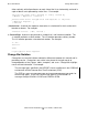
SCSI Extender Configuration SCSI Extender Overview Figure 1-1. SCSI Extender Configuration SCSI (75ft, Max) NonStop Server Fibre (10 km Max) SCSI Extender Bridge SCSI-to-Fibre Extender Fibre-to-SCSI Extender SCSI (75ft, Max) Tape Drive For the 10 kilometer maximum distance, you must use single-mode fiber cables between the SCSI extenders. If you are using multimode fiber cables, the maximum distance is 550 meters.
SCSI Extender SCSI Extender Overview SCSI Extender The SCSI extender shown in Figure 1-2 is a 1U unit with an integrated power supply. It is highly reliable and delivers a new level of throughput, speed, and distance. It can deliver data as fast as the destination buffer is able to receive it. A pair of SCSI extenders connect a supported storage device to a supported SCSI port on a NonStop S-series server: • • SCSI-to-Fiber extender (CTSFE) Fiber-to-SCSI extender (CTFSE) Figure 1-2. SCSI Extender 1.
Fibre Channel Port SCSI Extender Overview The SCSI extender has several types of data connections: • • • • One SCSI channel port on the Fibre-to-SCSI extender connects to the SCSI port on a supported storage device. One SCSI channel port on the SCSI-to-Fibre extender connects to a supported SCSI port on the NonStop S-Series Server. For more information, refer to Table 1-4, Supported SCSI Ports, on page 1-6. Fibre Channel gigabaud interface connector [GBIC] connects to the other SCSI extender.
SCSI IDs SCSI Extender Overview Table 1-4.
2 Installing a SCSI Extender Enclosure SCSI Extender Enclosure 2-2 Installing a SCSI Extender Enclosure 2-3 Supported Stacking Configurations 2-3 SCSI Extender Installation and User’s Guide— 522347-002 2 -1
SCSI Extender Enclosure Installing a SCSI Extender Enclosure SCSI Extender Enclosure The SCSI Extender Enclosure is shown in Figure 2-1 . Figure 2-1. SCSI Extender Enclosure 20.50 inches 20.75 inches Table 2-1. SCSI Extender Enclosure Specifications Specification Value Weight with base and all components 156 pounds (70.76 kilograms) Weight without base and all components installed 131 pounds (59.42 kilograms) Weight without base and all components 75 pounds (34.02 kilograms) Height 20.
Installing a SCSI Extender Enclosure Installing a SCSI Extender Enclosure Installing a SCSI Extender Enclosure The SCSI extenders are installed in a SCSI extender enclosure. Each enclosure can hold up to seven SCSI extenders as shown in Figure 2-2. Figure 2-2. Seven SCSI Extenders Installed in a SCSI Extender Enclosure Supported Stacking Configurations To stack enclosures, refer to the NonStop S-Series Service Provider Supplement in the Hardware Service and Maintenance Library.
Installing a SCSI Extender Enclosure Supported Stacking Configurations Figure 2-3.
Installing a SCSI Extender Enclosure Supported Stacking Configurations Figure 2-4.
Installing a SCSI Extender Enclosure Supported Stacking Configurations Figure 2-5.
3 Installing a SCSI Extender Overview of an Initial Installation 3-1 Unpacking a SCSI Extender 3-2 Installing Mounting Brackets in a Customer-Provided Rack 3-2 Installing a SCSI Extender in an Enclosure or Customer-Provided Rack 3-3 Overview of an Initial Installation 1. Unpack the SCSI extenders. Refer to Unpacking a SCSI Extender on page 3-2. 2.
Installing a SCSI Extender Unpacking a SCSI Extender Unpacking a SCSI Extender 1. Place the shipping container on a flat, clean, stable surface. 2.
Installing a SCSI Extender Installing a SCSI Extender in an Enclosure or Customer-Provided Rack Installing a SCSI Extender in an Enclosure or Customer-Provided Rack 1. Place the SCSI extender bottom down on a flat surface facing forward. 2. Place one L-bracket flush against the left side of the SCSI extender and fasten it with two 1” screws. 3. Place one L-bracket flush against the right side of the SCSI extender and fasten it with two 1” screws. 4.
Installing a SCSI Extender Installing a SCSI Extender in an Enclosure or Customer-Provided Rack SCSI Extender Installation and User’s Guide— 522347-002 3 -4
4 Cabling and Powering On the SCSI Extenders Overview of Cabling and Powering on the SCSI Extenders 4-2 Connect the Fiber-to-SCSI extender (CTFSE) to a Supported Storage Device 4-2 Connect the Fiber Cable Between the SCSI Extenders 4-3 Connect the SCSI-to-Fiber extender (CTSFE) to a Supported SCSI Port on the NonStop S-Series Server 4-3 Power On the Storage Device 4-4 Power On the Fiber-to-SCSI extender (CTFSE) 4-4 Power On the SCSI-to-Fiber extender (CTSFE) 4-4 SCSI Extender Installation and User’s Guide
Overview of Cabling and Powering on the SCSI Extenders Cabling and Powering On the SCSI Extenders Overview of Cabling and Powering on the SCSI Extenders To cable on power on the SCSI extenders: 1. Connect the Fiber-to-SCSI extender (CTFSE) to a Supported Storage Device on page 4-2. 2. Connect the Fiber Cable Between the SCSI Extenders on page 4-3. 3. Connect the SCSI-to-Fiber extender (CTSFE) to a Supported SCSI Port on the NonStop S-Series Server on page 4-3. 4.
Cabling and Powering On the SCSI Extenders Connect the Fiber Cable Between the SCSI Extenders Connect the Fiber Cable Between the SCSI Extenders Note. It does not matter which connector goes into which side, just as long as they are switched between the SCSI extenders. It is important to make sure that the fiber cable is switched between the SCSI extenders. The transmit plugs need to be inserted into the receive ports on both of the SCSI extenders.
Cabling and Powering On the SCSI Extenders Power On the Storage Device Power On the Storage Device Refer to the instructions for the specific storage device. Power On the Fiber-to-SCSI extender (CTFSE) 1. Insert the power cord into the AC Power Receptacle. 2. Connect the power cord to an AC power source. 3. Power on the Fiber-to-SCSI extender (CTFSE). Power On the SCSI-to-Fiber extender (CTSFE) Caution.
5 Subsystem Control Facility (SCF) Configuration Configure the SCSI Extenders 5-1 Configure the Storage Devices 5-2 Configure the SCSI Extenders 1. Ensure that both SCSI extenders are installed properly. 2. Save the current $SYSTEM.ZSYSCONF.CONFIG file using the SCF SAVE command. The SAVE command is described in the SCF Reference Manual for GSeries RVUs. 3. For each SCSI extender, use the SCF ADD SCSI command to add the SCSI extender to the system configuration database. Note.
Subsystem Control Facility (SCF) Configuration Configure the Storage Devices This example adds a Fiber-to-SCSI extender (CTFSE) named $FSROUT1 to the system configuration database: -> ADD SCSI $FSROUT1,SENDTO STORAGE,PRIMARY LOCATION (1,1,52),PRIMARYSAC 2,PRIMARYCPU 0,BACKUPCPU 1,SCSIID 9 Note. The ID for a Fiber-to-SCSI extender (CTFSE) is preconfigured to 9 and must not be changed. In this example: • • • • • • The $FSROUT1 is an example; however, you can use any device name.
6 Operating and Troubleshooting the SCSI Extender TSM and OSM 6-1 Visual Inspection 6-1 Technical Support 6-1 LED Status Lights 6-2 TSM and OSM Refer to TSM or OSM online help for information about using TSM or OSM for monitoring and troubleshooting tape drives and SCSI extenders connected to tape drives. You cannot use TSM or OSM to monitor tape libraries or SCSI extenders connected to tape libraries.
Technical Support Operating and Troubleshooting the SCSI Extender Technical Support If you cannot correct the problem and the SCSI extenders are still not functioning properly, contact your service provider. LED Status Lights LED status lights are on the rear panel of the SCSI extender as shown in Figure 6-1 on page 6-3. Figure 6-1. LED Status Lights LED Status Lights Table 6-1 on page 6-2 describes the LED Status Lights. Table 6-1.
Operating and Troubleshooting the SCSI Extender SCSI Extender Installation and User’s Guide— 522347-002 6 -3 LED Status Lights
Operating and Troubleshooting the SCSI Extender SCSI Extender Installation and User’s Guide— 522347-002 6 -4 LED Status Lights
Index C T Configuring SCSI extenders 5-1 Troubleshooting using TSM 6-1 using visual inspection 6-1 TSM for troubleshooting 6-1 D Devices, supported for connection to SCSI extenders 1-2 F Fiber cables 1-5 Fibre channel port 1-5 I Installing in a customer-provided rack 3-2 SCSI extender enclosure 2-2 tabletop version 3-2 R Rack, installing in a customer-provided 3-2 S SCSI IDs 1-6 port on extender 1-5 supported ports on server 1-6 SCSI extender description 1-4 SCF configuration 5-1 unpacking 3-2 SCSI
T Index SCSI Extender Installation and User’s Guide— 522347-002 Index -2