ServerNet Cluster 6770 Hardware Installation and Support Guide Abstract This guide describes the installation and support of the HP NonStop™ ServerNet Cluster 6770 components: the ServerNet II Switch, uninterruptible power supply (UPS), and AC transfer switch. Product Version N.A. Supported Release Version Updates (RVUs) This guide supports G06.14 and H06.03 and all subsequent G-series and H-series release version updates until otherwise indicated by its replacement publication.
Document History Part Number Product Version Published 522544-002 N.A. July 2006 522544-001 N.A. November 2001 429595-001 N.A. April 2001 426921-001 N.A.
ServerNet Cluster 6770 Hardware Installation and Support Guide Glossary Index What’s New in This Guide vii Guide Information vii New and Changed Information About This Guide ix Where to Find More Information Notation Conventions x Figures Tables viii ix 1.
2. Planning for the ServerNet Cluster Switch (continued) Contents 2. Planning for the ServerNet Cluster Switch (continued) Planning for Environmental Requirements 2-15 Planning for Power to the ServerNet Cluster Switch AC Power Requirements 2-16 Planning to Respond to Power Failures 2-16 2-16 3.
. Installing Switch Components in an EIA Standard Rack (continued) Contents 5. Installing Switch Components in an EIA Standard Rack (continued) Task 7: Install the ServerNet II Switch Into the Rack 5-8 Task 8: Connect and Route the Cables and Cords 5-9 Task 9: Power On the Components 5-9 6. Connecting the ServerNet Fiber-Optic Cables Labeling the Cables 6-1 Routing and Connecting the Cables 6-3 7.
A. Part Numbers Contents A. Part Numbers B. Electrostatic Discharge (ESD) Guidelines C. Firmware Notes Required SPRs C-2 Checking the Cluster Switch Firmware and Configuration Versions Updating the Firmware and Configuration C-7 C-5 Safety and Compliance Index Figures Figure 1-1. Figure 1-2. Figure 1-3. Figure 1-4. Figure 1-5. Figure 1-6. Figure 1-7. Figure 1-8. Figure 1-9. Figure 1-10. Figure 1-11. Figure 1-12. Figure 1-13. Figure 1-14. Figure 2-1. Figure 2-2. Figure 2-3. Figure 2-4. Figure 2-5.
Figures (continued) Contents Figures (continued) Figure 6-2. Figure 6-3. Figure 7-1. Figure 7-2. Figure 7-3. Figure 7-4. Figure 8-1. Figure 8-2. Figure 8-3. Figure 8-4. Figure 8-5. Figure 8-6. Figure 8-7. Figure 8-8.
Tables Contents ServerNet Cluster 6770 Hardware Installation and Support Guide —522544-002 vi
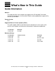
What’s New in This Guide Guide Information ServerNet Cluster 6770 Hardware Installation and Support Guide Abstract This guide describes the installation and support of the HP NonStop™ ServerNet Cluster 6770 components: the ServerNet II Switch, uninterruptible power supply (UPS), and AC transfer switch. Product Version N.A. Supported Release Version Updates (RVUs) This guide supports G06.14 and H06.
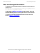
What’s New in This Guide New and Changed Information New and Changed Information This document has been updated throughout to incorporate changes to product and comapany names. Information about using the NonStop Open System Management (OSM) Interface has been added wherever using TSM is described. The part numbers in Appendix A, Part Numbers have been removed. You can find information about part numbers in the Part Numbers topic of the Service Information section of the NTL Support and Service Library.
About This Guide This guide provides information about how to plan, install, troubleshoot, and replace components of a 6770 ServerNet Cluster Switch: • • • ServerNet II Switch AC transfer switch Uninterruptible power supply (UPS) Where to Find More Information For more information about ServerNet clusters, refer to the following manuals: • • ServerNet Cluster Manual NonStop S-Series Service Provider Supplement Support and Service Library These NTL Support and Service library categories provide procedu
About This Guide Notation Conventions Notation Conventions Hypertext Links Blue underline is used to indicate a hypertext link within text. By clicking a passage of text with a blue underline, you are taken to the location described. For example: This requirement is described under Backup DAM Volumes and Physical Disk Drives on page 3-2. General Syntax Notation The following list summarizes the notation conventions for syntax presentation in this manual. UPPERCASE LETTERS.
About This Guide General Syntax Notation each side of the list, or horizontally, enclosed in a pair of brackets and separated by vertical lines. For example: FC [ num ] [ -num] [ text] K [ X | D ] address-1 { } Braces. A group of items enclosed in braces is a list from which you are required to choose one item. The items in the list may be arranged either vertically, with aligned braces on each side of the list, or horizontally, enclosed in a pair of braces and separated by vertical lines.
About This Guide Change Bar Notation Line Spacing. If the syntax of a command is too long to fit on a single line, each continuation line is indented three spaces and is separated from the preceding line by a blank line. This spacing distinguishes items in a continuation line from items in a vertical list of selections. For example: ALTER [ / OUT file-spec / ] LINE [ , attribute-spec ]...
1 Introduction to the ServerNet Cluster Switch (Model 6770) This section includes these topics: ServerNet Clusters and External ServerNet Fabrics on page 1-2 Modular ServerNet Expansion Boards (MSEBs) on page 1-5 ServerNet Cluster Switch on page 1-5 ServerNet Cluster Switch Enclosure on page 1-6 EIA Standard Rack-Mount on page 1-7 ServerNet II Switch on page 1-7 AC Transfer Switch on page 1-10 Uninterruptible Power Supply (UPS) on page 1-10 Cable and Power Cord Connections on page 1-13 Power Cords on page
Introduction to the ServerNet Cluster Switch (Model 6770) ServerNet Clusters and External ServerNet Fabrics ServerNet Clusters and External ServerNet Fabrics The ServerNet Cluster Switch, model 6770, connects NonStop S-series servers in a ServerNet cluster. Dual (X and Y) external ServerNet fabrics provide fault tolerance for a ServerNet cluster. The peer external ServerNet fabric takes control if one external fabric fails.
Introduction to the ServerNet Cluster Switch (Model 6770) ServerNet Clusters and External ServerNet Fabrics Two switches per fabric support up to sixteen nodes (Figure 1-2) in a ServerNet cluster. Figure 1-2.
Introduction to the ServerNet Cluster Switch (Model 6770) ServerNet Clusters and External ServerNet Fabrics Three switches per fabric support up to twenty-four nodes (Figure 1-3) in a ServerNet cluster. Figure 1-3.
Introduction to the ServerNet Cluster Switch (Model 6770) Modular ServerNet Expansion Boards (MSEBs) Modular ServerNet Expansion Boards (MSEBs) The MSEBs route ServerNet packets out of each node and onto the external ServerNet fabrics. MSEBs are similar to system expansion boards (SEBs) but use plug-in cards (PICs) to provide a choice of connection media (ECL, fiber-optic, or serial copper). Fiber-optic ServerNet cables connect the MSEBs in each node to the ServerNet II Switches.
Introduction to the ServerNet Cluster Switch (Model 6770) • ServerNet Cluster Switch Enclosure AC Transfer Switch on page 1-10 provides dual power rails for the UPS and ServerNet II Switch. The ServerNet Cluster Switch is available in an enclosure or in an EIA standard rackmount (you must provide the rack). ServerNet Cluster Switch Enclosure When you receive a ServerNet Cluster Switch enclosure, the ServerNet II switch, AC transfer switch, and UPS are already installed inside the enclosure.
Introduction to the ServerNet Cluster Switch (Model 6770) EIA Standard Rack-Mount EIA Standard Rack-Mount The components of the ServerNet Cluster Switch: ServerNet II Switch, AC transfer switch, UPS, and a rack-mount kit are shipped separately to be installed at the customer site in a customer-supplied EIA standard rack. Table 1-1.
Introduction to the ServerNet Cluster Switch (Model 6770) ServerNet II Switch Figure 1-6. Side and Back of ServerNet II Switch VST810.vsd Front Panel of the ServerNet II Switch The ServerNet II Switch provides power, status, and activity LEDs for monitoring the operation of the switch. Refer to Using the LEDs to Monitor a ServerNet II Switch on page 8-6 for more information. Figure 1-7. ServerNet II Switch VST919.
Introduction to the ServerNet Cluster Switch (Model 6770) ServerNet II Switch ServerNet II Switch PICs The twelve output ports (Figure 1-8) on a ServerNet II Switch are numbered 0 through 11: • • Single-wide PICs in ports 0 through 7 connect the switch to a node using singlemode fiber-optic ServerNet cables. Double-wide PICs in ports 8 through 11 connect switches on the same external fabric together. Note. Ports 8 and 9 are located to the right of ports 10 and 11. Figure 1-8.
Introduction to the ServerNet Cluster Switch (Model 6770) AC Transfer Switch Figure 1-9. AC/DC Power Supply of the ServerNet II Switch VST807.vsd AC Transfer Switch The AC transfer switch allows the ServerNet II Switch and related components to be powered from two independent AC power rails: • • The primary power rail connects to an AC line cord. The secondary power rail connects to a different AC line cord. Replacement by a service provider trained by HP is recommended.
Introduction to the ServerNet Cluster Switch (Model 6770) Uninterruptible Power Supply (UPS) Figure 1-10. Rear Panel of the UPS (North American Version) REPO Port IEC-320 Inlet Monitor Port Power Outlet VST901.vsd Power Outlet Because providing power to any device other than the ServerNet II Switch is not supported, all but one of the power outlets on the UPS are covered by a metal flange.
Introduction to the ServerNet Cluster Switch (Model 6770) Uninterruptible Power Supply (UPS) 60Vdc maximum, 30Vac RMS maximum, and 20 mA maximum. For fault tolerance, use a single set of contacts per each UPS. Note.
Introduction to the ServerNet Cluster Switch (Model 6770) Cable and Power Cord Connections Cable and Power Cord Connections Several cables and power cords connect the components of the ServerNet Cluster Switch together, to the AC power sources, and to the ServerNet clusters. Figure 1-13. Logical Diagram of Connections VST930.vsd Power Cords Four power cords are used to connect the ServerNet Cluster Switch. These power cords connect: • • • • The AC transfer switch to the primary AC power source.
Introduction to the ServerNet Cluster Switch (Model 6770) Fiber-Optic ServerNet Cables Fiber-Optic ServerNet Cables Single-mode, fiber-optic ServerNet cables connect each node to the ServerNet II Switches on each fabric. Connections Between the ServerNet II Switch PICs and MSEB PICs A fiber-optic ServerNet cable from a ServerNet port numbered 0 through 7 on one of the ServerNet II Switches connects to an MSEB in each node.
Introduction to the ServerNet Cluster Switch (Model 6770) Fiber-Optic ServerNet Cables The maximum cable distance between ServerNet II Switches on the same fabric depends on your current software. If required, you must install the appropriate SPRs to the base software releases before cabling the switches together. For more information, see the ServerNet Cluster Manual. Table 1-3.
Introduction to the ServerNet Cluster Switch (Model 6770) Fiber-Optic ServerNet Cables ServerNet Cluster 6770 Hardware Installation and Support Guide —522544-002 1- 16
2 Planning for the ServerNet Cluster Switch This section includes these topics: Planning to Install a ServerNet Cluster Switch on page 2-1 Required Hardware on page 2-4 Required Software on page 2-4 Required Firmware and Configuration on page 2-6 Planning for the ServerNet Cluster Switch Hardware Configurations on page 2-10 Planning for Installation in an EIA Standard Rack on page 2-10 Planning for ServerNet Cluster Switch Enclosures on page 2-10 Planning for Cable and Power Cord Connections on page 2-12 C
Planning for the ServerNet Cluster Switch Planning to Install a ServerNet Cluster Switch or update hardware, software, firmware, and the system configuration database. To plan for each task: Planning Task Documentation 1. Make sure you have all the required hardware. Required Hardware on page 2-4 2.
Planning for the ServerNet Cluster Switch Planning Task f. If you have more than one switch per fabric, add the switch to an existing ServerNet cluster. Planning to Install a ServerNet Cluster Switch Documentation ServerNet Cluster Manual Add Switch guided configuration tool (TSM) Update Topology action of the ServerNet Cluster Resource (OSM Service Connection online help) 4. Plan to add nodes to a ServerNet cluster. ServerNet Cluster Manual a.
Required Hardware Planning for the ServerNet Cluster Switch Planning Task f. Install MSEBs in slots 51 and 52 located in the group 01 enclosure of each node. g. Update the system configuration database on each node. Documentation Replace SEB or MSEB guided replacement procedure (TSM) Replace action of the MSEB (OSM) Required System Configuration on page 2-6 ServerNet Cluster Manual h.
Required Software Planning for the ServerNet Cluster Switch Table 2-1. Required Software Hardware Minimum Base Software Release Minimum Software Release With SPRs Installed MSEB G06.09 and later G-series RVUs None required Node in a maximum 8-node ServerNet cluster G06.09 and later G-series RVUs None required Node in a maximum 16-node ServerNet cluster G06.12 and later G-series RVUs G06.09 through G06.11 Node in a maximum 24-node ServerNet cluster G06.14 and later G-series RVUs G06.
Required Firmware and Configuration Planning for the ServerNet Cluster Switch Required Firmware and Configuration Required System Configuration Communication between the ServerNet II Switch and the nodes depends on the processes listed in Table 2-2 being configured and in a STARTED state. After you have installed the ServerNet Cluster Switches, make sure that each node in a ServerNet cluster is properly configured and that all required processes are started. Table 2-2.
Planning for the ServerNet Cluster Switch Required Firmware and Configuration Refer to the following manuals for more information about the commands supported for the SCF interface to these subsystems: Table 2-3.
Required Firmware and Configuration Planning for the ServerNet Cluster Switch Do not perform firmware upgrades and configuration upgrades simultaneously. Starting one while the other is in progress will abort the one in progress. Table 2-4.
Required Firmware and Configuration Planning for the ServerNet Cluster Switch Figure 2-2. ServerNet Node Numbers Using Two-Lane Links ServerNet Node Numbers 1 9 2 10 0 3 4 0 1 8 10 1 2 9 11 2 X1/Y1 ServerNet II Switch Port Numbers 3 5 4 5 6 6 11 12 3 X2/Y2 ServerNet II Switch Port Numbers 4 11 8 5 10 9 6 13 14 7 7 15 7 8 X3/Y3 ServerNet II Switch Port Numbers 0 17 18 8 9 1 2 19 3 20 16 10 11 5 6 4 21 22 7 23 24 ServerNet Node Numbers VST120.
Planning for the ServerNet Cluster Switch Planning for the ServerNet Cluster Switch Hardware Configurations Planning for the ServerNet Cluster Switch Hardware Configurations When planning the location of the ServerNet Cluster Switch and each of the nodes, consider the following: • • The length of the fiber-optic ServerNet cables between each ServerNet Cluster Switch and each node. For more information, refer to Planning for Cable and Power Cord Connections on page 2-12.
Planning for the ServerNet Cluster Switch Planning for ServerNet Cluster Switch Enclosures . Figure 2-3. Stacking ServerNet Cluster Switch Enclosures To avoid cabling errors, place the X-fabric and the Y-fabric switches in different locations ServerNet Cluster Switch (Y Fabric) ServerNet Cluster Switch (X Fabric) Do not stack ServerNet Cluster switches on top of a double-high stack. Do not stack ServerNet Cluster Switches on top of each other.
Planning for the ServerNet Cluster Switch Planning for Cable and Power Cord Connections Planning for Cable and Power Cord Connections Because the ServerNet Cluster Switch requires many cables and power cords, careful planning is essential.
Choosing Fiber-Optic ServerNet cables Planning for the ServerNet Cluster Switch Figure 2-4. Maximum Distance Between Nodes With One ServerNet II Switch Per Fabric 160 m 80 m Fiber-Optic Cable 80 m Fiber-Optic Cable Group 01 \A X1 Cluster Switch Group 01 \B (X Fabric Shown) VST038.vsd • Depending on your software, either 80 meters or one kilometer is the maximum cable distance between ServerNet II Switches on the same fabric.
Choosing Fiber-Optic ServerNet cables Planning for the ServerNet Cluster Switch Figure 2-5. Maximum Distance Between Nodes With a One Kilometer Link Between Switches Group 01 \A Group 01 \B (X Fabric Shown) 1.16 km Maximum 80 m Fiber-Optic Cable 80 m Fiber-Optic Cable X1 Cluster Switch X2 Cluster Switch 1 km Maximum for Fiber-Optic Cables Between Cluster Switches X3 Cluster Switch 1.16 km Maximum 1.16 km Maximum 80 m Fiber-Optic Cable Group 01 \C VST122.
Planning for the ServerNet Cluster Switch Installing Fiber-Optic ServerNet Cables Installing Fiber-Optic ServerNet Cables Before installing fiber-optic cables, note the following considerations: Consideration Additional Notes Review specifications first. Review the cable/connector specifications, routing procedures, and your building’s floor plan where the fiber-optic cables are to be routed. If you have questions or need further information, consult the global customer support center (GCSC).
Planning for Power to the ServerNet Cluster Switch Planning for the ServerNet Cluster Switch Planning for Power to the ServerNet Cluster Switch AC Power Requirements Make sure that your AC power meets these requirements for the ServerNet Cluster Switch.
Planning for the ServerNet Cluster Switch Planning to Respond to Power Failures The length of each dual power cord from the AC transfer switch is 2.5 meters (8.2 feet).
Planning for the ServerNet Cluster Switch Planning to Respond to Power Failures ServerNet Cluster 6770 Hardware Installation and Support Guide —522544-002 2- 18
3 Preparing to Install or Replace 6770 ServerNet Cluster Switch Components This section includes these topics: Preparing to Install Switch Components on page 3-1 Preparing to Replace Switch Components on page 3-1 Verifying Software and Firmware on page 3-2 Verifying the System Configuration on page 3-3 Verifying System Operations on page 3-4 Preparing to Install Switch Components 1. Verify that the MSEBs are installed in slot 51 and slot 52 of each node you will be connecting to. 2.
Preparing to Install or Replace 6770 ServerNet Cluster Switch Components Verifying Software and Firmware 3. Replace the component or contact your service provider. Component Refer to: AC Transfer Switch The Replace a Switch Component guided procedure. When using OSM, this procedure is launched by the Replace action of the Switch Module, the ServerNet II Switch, the AC Transfer Switch, or the UPS.
Preparing to Install or Replace 6770 ServerNet Cluster Switch Components Verifying the System Configuration 6. Verify that the firmware version for each SP is the same as the VPROC version in step 2. If any SP has a different version, refer to the OSM or TSM online help for information about updating your SP firmware.
Preparing to Install or Replace 6770 ServerNet Cluster Switch Components Verifying System Operations 4. If needed, start SANMAN. For example: -> START PROCESS $ZZKRN.#ZZSMN 5. Verify that SNETMON is in a STARTED state. For example: -> STATUS PROCESS $ZZKRN.#ZZSCL Note. The SUBSYS $ZZSCL object cannot be started until after the nodes are configured and the ServerNet fiber-optic cable to that node has been connected.
Preparing to Install or Replace 6770 ServerNet Cluster Switch Components Verifying the Status of the Internal ServerNet Fabric 2. From the system tab, right click the Internal_SvNet_X_Fabric. 3. Select Actions from the menu that is displayed. 4. From the Actions list, select Group Connectivity ServerNet Path Test. 5. Click Perform Action. A confirmation box asks whether you really want to run the test. 6. Click OK. 7. Monitor the status in the Action Status list. 8.
Preparing to Install or Replace 6770 ServerNet Cluster Switch Components Verifying the Status of the Internal ServerNet Fabric ServerNet Cluster 6770 Hardware Installation and Support Guide —522544-002 3 -6
4 Installing a ServerNet Cluster Switch Enclosure This section includes these topics: Stacking a ServerNet Cluster Switch Enclosure on page 4-1 Preinstalled Components and Cables on page 4-1 Installing the Enclosure on page 4-2 Configuring the ServerNet Cluster on page 4-3 Stacking a ServerNet Cluster Switch Enclosure If you order a ServerNet Cluster Switch enclosure to be stacked on a base system enclosure, the enclosure arrives already stacked.
Installing a ServerNet Cluster Switch Enclosure Installing the Enclosure Installing the Enclosure Task 1: Planning and Preparation 1. Review Section 1, Introduction to the ServerNet Cluster Switch (Model 6770) for a detailed description of the switch components, connections, cables, and cords. 2. Perform all the planning steps in Section 2, Planning for the ServerNet Cluster Switch . 3. Perform all the planning steps in the ServerNet Cluster Manual. 4.
Installing a ServerNet Cluster Switch Enclosure Task 3: Completing the Installation Task 3: Completing the Installation 1. Connect the ServerNet II Switch to the nodes as described in Section 6, Connecting the ServerNet Fiber-Optic Cables. 2. Push the ServerNet II Switch into the enclosure. 3. Replace the blank panels above the ServerNet II Switch. 4. Power on the cluster switch as described in Powering On a ServerNet Cluster Switch on page 7-2. 5.
Installing a ServerNet Cluster Switch Enclosure Configuring the ServerNet Cluster ServerNet Cluster 6770 Hardware Installation and Support Guide —522544-002 4 -4
5 Installing Switch Components in an EIA Standard Rack This section includes these topics: Procedure Summary on page 5-2 Task 1: Assemble the Required Tools on page 5-3 Task 2: Verify That You Have All the Parts in the Rack-Mount Kit on page 5-3 Task 3: Install the Cage Nuts on page 5-4 Task 4: Install the Rails and Cable-Management Assembly on page 5-6 Task 4a: Install the UPS Rails on page 5-6 Task 4b: Install the Cable-Management Tray on page 5-6 Task 4c: Install the Cable-Management Assembly on page 5-
Installing Switch Components in an EIA Standard Rack Procedure Summary Procedure Summary The ServerNet II Switch, AC transfer switch, and UPS are shipped separately. Install these components in the rack as follows: 1. Task 1: Assemble the Required Tools on page 5-3 2. Task 2: Verify That You Have All the Parts in the Rack-Mount Kit on page 5-3. 3. Task 3: Install the Cage Nuts on page 5-4 4. Task 4: Install the Rails and Cable-Management Assembly on page 5-6. 5. Task 5: Install the UPS on page 5-8.
Installing Switch Components in an EIA Standard Rack Task 1: Assemble the Required Tools Task 1: Assemble the Required Tools You need the following tools: • • • • • • Cage-nut fitting tool T25 Torx screwdriver T20 Torx screwdriver 7 mm wrench Phillips screwdriver Nut driver Task 2: Verify That You Have All the Parts in the Rack-Mount Kit The rack-mount kit contains the following parts: Quantity Description 1 UPS left fixed rail 1 UPS right fixed rail 2 UPS rail brackets 1 Cable-management tray
Installing Switch Components in an EIA Standard Rack Task 3: Install the Cage Nuts Task 3: Install the Cage Nuts Some T25 Torx screws need cage nuts. You must install the cage nuts in the front of the rack in a different pattern than in the back of the rack. 1. At the back of the rack, use the cage-nut fitting tool to install 8 cage nuts in the locations shown in Figure 5-1 . Figure 5-1.
Installing Switch Components in an EIA Standard Rack Task 3: Install the Cage Nuts 2. At the front of the rack, install 12 cage nuts in the locations shown in Figure 5-2. Figure 5-2. Locations of Cage Nuts in the Front of the Rack Cage Nuts for Blank Panels Cage Nuts for ServerNet II Switch Rail Cage Nuts for Blank Panel Cage Nuts for AC Transfer Switch VST921.
Installing Switch Components in an EIA Standard Rack Task 4: Install the Rails and Cable-Management Assembly Task 4: Install the Rails and CableManagement Assembly Task 4a: Install the UPS Rails 1. Assemble the following hardware and tools: • • • • 2 UPS fixed rails (left and right) 2 UPS rail brackets 12 M5 Torx screws T25 screwdriver 2. Use a T25 Torx screwdriver and 4 M5 Torx screws to attach the UPS rail brackets to the UPS rails.
Installing Switch Components in an EIA Standard Rack Task 4c: Install the Cable-Management Assembly 2. At the back of the rack: a. Place the cable-management tray on top of the UPS fixed rails. b. Use a T25 Torx screwdriver and two M5 Torx screws to attach the cable management tray to the outside of the back of the rack. c. On top of the cable management tray, place a kep nut on each of the two studs on top of the UPS fixed rail. d. Use a nut driver to fasten the kep nuts.
Installing Switch Components in an EIA Standard Rack Task 5: Install the UPS 4. Mount the assembled ServerNet II Switch slide rails into the inside of the rack: a. Orient the slide rails so that the metal stop tab at one end of the rails is to the back of the rack. b. Align the slide rails at the level of the bottom hole of the cable-management assembly bracket that you installed in step 3 of task 4c. c. Attach each slide bracket to the rack using one M5 screw. d.
Installing Switch Components in an EIA Standard Rack Task 8: Connect and Route the Cables and Cords 4. Push the ServerNet II Switch into the rack. 5. Pull the ServerNet II switch out slowly to make sure that the slide lock catches. Make sure that the ServerNet II Switch slides in and out easily. 6. Leave the ServerNet II Switch fully extended during the rest of the installation. Task 8: Connect and Route the Cables and Cords 1.
Installing Switch Components in an EIA Standard Rack Task 9: Power On the Components ServerNet Cluster 6770 Hardware Installation and Support Guide —522544-002 5- 10
6 Connecting the ServerNet Fiber-Optic Cables This section includes these topics: Labeling the Cables on page 6-1 Routing and Connecting the Cables on page 6-3 Labeling the Cables Label each fiber-optic ServerNet cable on both ends. On each label, note where that end of the cable connects.
Labeling the Cables Connecting the ServerNet Fiber-Optic Cables Figure 6-1. Labeling Fiber-Optic ServerNet Cables VST041.
Routing and Connecting the Cables Connecting the ServerNet Fiber-Optic Cables Routing and Connecting the Cables 1. From the service side, route the fiber-optic ServerNet cables through the enclosure or rack toward the ServerNet ports. 2. For each node, connect one fiber-optic ServerNet cable to one of the ports numbered 0 through 7 on the ServerNet II Switch on the X fabric. Note.
Connecting the ServerNet Fiber-Optic Cables Routing and Connecting the Cables a. If dust caps are installed on the ceramic ferrule tips of each connector, remove the dust caps. Figure 6-2. Fiber-optic ServerNet Cable Dust Caps VST056.vsd b. Inspect each fiber-optic cable connector. See Figure 6-3. • • • Make sure the ferrule housing and the ceramic ferrule tip are visible. The ferrule housing should be at least flush with the connector housing.
Connecting the ServerNet Fiber-Optic Cables Routing and Connecting the Cables Figure 6-3. Inspecting Fiber-Optic Cable Connectors VST003.vsd 3. Align the keys on the connector body with the key slots on the receptacle of the ServerNet II Switch. 4. Insert the connector plug into the receptacle, squeezing the connector body gently between your thumb and forefinger as you insert it. Push the connector plug straight into the receptacle until the connector plug clicks into place. 5.
Connecting the ServerNet Fiber-Optic Cables Routing and Connecting the Cables ServerNet Cluster 6770 Hardware Installation and Support Guide —522544-002 6 -6
7 Powering On and Powering Off a ServerNet Cluster Switch This section includes these topics: Powering On a ServerNet Cluster Switch on page 7-2 Connecting to the Remote EPO Port, if Required on page 7-3 Connecting an AC Transfer Switch to AC Power on page 7-3 Powering On a UPS on page 7-4 Powering On a ServerNet II Switch on page 7-5 Powering Off a ServerNet Cluster Switch on page 7-6 Powering Off a ServerNet II Switch on page 7-6 Disconnecting the AC Power Cords on page 7-7 ServerNet Cluster 6770 Hardwa
Powering On and Powering Off a ServerNet Cluster Switch Powering On a ServerNet Cluster Switch Powering On a ServerNet Cluster Switch • To power on a ServerNet Cluster Switch for the first time: 1. Review the information about power planning in Planning for Power to the ServerNet Cluster Switch on page 2-16. 2. Connect to the Remote EPO port on the UPS, if required: a. Review the information in Remote Emergency Power Off (EPO) Port on page 1-11. b.
Powering On and Powering Off a ServerNet Cluster Switch Connecting to the Remote EPO Port, if Required Connecting to the Remote EPO Port, if Required To connect to the remote emergency power-off (EPO) port on the UPS, have an electrician perform the following steps: 1. From the back of the enclosure or rack, remove the pluggable terminal block from the remote EPO port as shown in Figure 7-1. Figure 7-1. Removing the Pluggable Terminal Block VST903.vsd 2.
Powering On and Powering Off a ServerNet Cluster Switch Powering On a UPS Powering On a UPS When AC power is available to the UPS from the AC transfer switch for the first time, a self test is initiated automatically. The front panel LEDs will go on and off during the self test. If the self test finishes successfully, the UPS enters Standby mode. Note. The self-test cannot be initiated if the batteries are less than 90% charged; a portion of the self-test requires battery power.
Powering On and Powering Off a ServerNet Cluster Switch Powering On a ServerNet II Switch Powering On a ServerNet II Switch Note. After powering off a ServerNet II Switch, you must wait 30 seconds before powering it back on again so that the voltage can discharge fully and that proper initialization can occur. If you do not wait 30 seconds, the ServerNet II Switch might power on in a non-operational state, and all LEDs will be stuck on. Powering off and back on again after 30 seconds corrects the problem.
Powering On and Powering Off a ServerNet Cluster Switch Powering Off a ServerNet Cluster Switch Powering Off a ServerNet Cluster Switch Powering Off a ServerNet II Switch You can power off the ServerNet II Switch from either the UPS or the ServerNet II Switch itself. If you are replacing a ServerNet II Switch or disconnecting the ServerNet II Switch from the UPS for any reason, you must power off the ServerNet II Switch from the UPS. Note.
Powering On and Powering Off a ServerNet Cluster Switch Disconnecting the AC Power Cords 2. Check the LEDs on the UPS: • • Check that the green power-on LED (16) is unlit. This LED indicates whether power is available to the ServerNet II Switch. The green battery charge LEDs (6 through 8) continue to show whether the UPS battery is fully charged. 3. Check that the green power-on LED on the ServerNet II Switch is unlit. • To power off the ServerNet II Switch directly: 1.
Powering On and Powering Off a ServerNet Cluster Switch Disconnecting the AC Power Cords ServerNet Cluster 6770 Hardware Installation and Support Guide —522544-002 7 -8
8 Troubleshooting This section includes these topics Determining the Cause of a Problem on page 8-1 Monitoring a ServerNet Cluster Switch on page 8-2 Monitoring a ServerNet II Switch on page 8-6 Monitoring a UPS on page 8-10 Monitoring an AC Transfer Switch on page 8-16 Verifying Proper Operation on page 8-18 Verifying the AC Power on page 8-18 Verifying the Fabric LED on a ServerNet II Switch on page 8-19 Verifying the Connection Between a ServerNet II Switch and a Node on page 8-20 Verifying the Connect
Monitoring a ServerNet Cluster Switch Troubleshooting • • • ° Does a light-emitting diode (LED), an OSM or TSM alarm, or event message indicate a problem? ° ° Is there a clear indication of one problem, or are there a number of problems? Do all indications consistently point to the same cause, or could the symptoms indicate a number of causes? Where is this problem occurring? ° If a problem is occurring on both ServerNet II Switches, the problem might be caused by the software or system configura
Using OSM or TSM to Monitor a ServerNet Cluster Switch Troubleshooting 2. From the tree pane, select the Cluster tab. Figure 8-1. Cluster Tab VST900.vsd 3. From the Cluster tab: a. Double-click External_ServerNet_X_Fabric or External_ServerNet_Y_Fabric. b. Select Switch_X_GUID_nnnnn or Switch_Y_GUID_nnnnn. Using the OSM Service Connection The OSM Service connection does not have a cluster tab, so you do not need to switch between cluster resources and system resources.
Troubleshooting Using OSM or TSM to Monitor a ServerNet Cluster Switch Figure 8-2. Alarms Tab VST801.vsd 1. Double click an alarm for additional information. The Alarm Detail dialog box is displayed. 2. If you have value-added diagnostics enabled, click Repair Actions for recovery procedures. Checking the Attributes Tab The Attributes tab in the details pane provides information about the ServerNet II Switch, UPS, and AC transfer switch. Note.
Using OSM or TSM to Monitor a ServerNet Cluster Switch Troubleshooting Figure 8-3. Cluster Switch Attributes VST950.
Monitoring a ServerNet II Switch Troubleshooting 3. Refer to the following for more information: • • • For information about the UPS Type, UPS ID, UPS Part Number, Battery Management, and Remaining Battery Time attributes, see Using OSM or TSM to Monitor a UPS on page 8-10. For information about the Primary Rail Power State and Backup Rail Power State attributes, see Using OSM or TSM to Monitor an AC Transfer Switch on page 8-16.
Monitoring a ServerNet II Switch Troubleshooting ServerNet II Switch LEDs: LED Function For information about how to interpret each LED, refer to: Green power LED Lit when a ServerNet II Switch is powered on. Table 8-3, Power-On and Fault LEDs, on page 8-9 Green X fabric and Y fabric LEDs Identifies the ServerNet SAN external fabric to which a ServerNet II Switch is connected. Table 8-2, Fabric LEDs, on page 8-8 Yellow fault LED Lit when an error condition occurs.
Monitoring a ServerNet II Switch Troubleshooting Table 8-1. ServerNet Port LEDs LED Status Meaning Recovery Action 8 through 11 LED is lit. A good connection has been established between a ServerNet II Switch port and another switch on the same fabric. No action is required. LED is not lit. If there is only one ServerNet II Switch per fabric, this status is expected. No action is required if another switch is not connected to these ports.
Monitoring a ServerNet II Switch Troubleshooting Table 8-2. Fabric LEDs LED Type Status Meaning Recovery Action Y LED (green) LED is lit on a switch for the Y fabric. The LED is set correctly. No action is required. LED is not lit on a switch for the Y fabric. The LED is not set correctly. Refer to Resetting the Fabric LED on the ServerNet II Switch on page 8-23. LED is lit on a switch for the X fabric. The LED is not set correctly.
Monitoring a UPS Troubleshooting Monitoring a UPS You can monitor the UPS using OSM or TSM and the LEDs on the front panel. If there is any discrepancy between the information provided by OSM or TSM and the LEDs on the UPS, contact your service provider before replacing the UPS. Using OSM or TSM to Monitor a UPS The following attributes of the Switch object provide information about the UPS. Refer to OSM or TSM online help for more information about these attributes. Table 8-4.
Monitoring a UPS Troubleshooting Using OSM or TSM Alarms to Monitor the UPS Several OSM and TSM alarms provide diagnostic and troubleshooting information about the UPS. Refer to Checking Alarms on page 8-3. If an alarm indicates a problem with an UPS, also check the LEDs on the UPS and the cable connections to the UPS. Using the LEDs to Monitor the UPS The front panel of the UPS contains 16 LEDs that provide information about the UPS. The LED numbers are not displayed on the front panel. Note.
Troubleshooting Monitoring a UPS Figure 8-5. LEDs on UPS VST907.
Monitoring a UPS Troubleshooting Table 8-5. AC Power LEDs on the UPS LED Type AC Input LEDs LED Status Meaning Recovery Action 1 LED is lit. The UPS is supplying battery power because the AC power voltage is higher than the allowable range. If this LED remains lit, have an electrician ensure that the proper AC power voltage is being supplied to the UPS. LED is flashing. The UPS is now supplying AC power because the voltage has returned to the allowable range.
Monitoring a UPS Troubleshooting Table 8-6. Battery LEDs on the UPS LED Type Battery Charge LEDs LED Status Meaning Recovery Action 6 (green) LED is lit and LEDs 7 and 8 are also lit. Batteries are between 67% and 100% charged. No action is required. 7 This LED and LED 8 are lit but LED 6 is not lit. Batteries are approximately 66% charged. Allow the UPS to charge the batteries for 24 hours. If the condition persists, contact your service provider to replace the UPS.
Monitoring a UPS Troubleshooting Table 8-6. Battery LEDs on the UPS LED Type Battery Service LED LED Status Meaning Recovery Action 10 LED is lit and the audio alarm sounds. If LED 10 is lit during power on the UPS, the battery voltage might be low if the UPS has been out of service for a long period. Allow the UPS to charge the batteries for 24 hours. Then initiate a self-test. If LED 10 continues to be lit, contact your service provider to replace the UPS.
Monitoring an AC Transfer Switch Troubleshooting Table 8-8. LED 15 on the UPS Color Meaning Recovery Action Green LED is lit, not lit, or flashing. This LED provides no useful information. No action is required. Table 8-9. Power-On LED 16 on the UPS Color Meaning Recovery Action Green LED is lit. Power for a ServerNet II Switch is available from the UPS outlet. No action is required. Green LED is not lit. Power for a ServerNet II Switch is not available from the UPS outlet.
Monitoring an AC Transfer Switch Troubleshooting Table 8-10. LEDs on the AC Transfer Switch LED Type AC Input LEDs LED Color Meaning Recovery Action PRIM IN LED is lit. The AC power voltage is present on the primary AC power rail. No action is required. LED is not lit. The AC power voltage is not present on the primary AC power rail. Refer to Verifying the AC Power on page 8-18. LED is lit. The AC power voltage is present on the secondary AC power rail. No action is required.
Verifying Proper Operation Troubleshooting Verifying Proper Operation If you detect a problem with a ServerNet Cluster Switch, use these procedures to verify proper operation. Verifying the AC Power 1. Check the LEDs on the AC transfer switch: a. Verify that all four green AC input LEDs on the AC transfer switch are lit. • • If these LEDs are lit, continue to the next step.
Verifying the Fabric LED on a ServerNet II Switch Troubleshooting 3. Check the LEDs on the ServerNet II Switch: a. Check that the green power-on LED on the ServerNet II Switch is lit. If this LED is not lit: a. Power-on the ServerNet II Switch again. b. Recheck the power-on LED. b. If the power-on LED on a switch continues to be unlit but the power-on LED 16 on the UPS and the AC transfer switch LEDs are lit, check the AC power cord from the UPS to the AC/DC power supply for the ServerNet II Switch.
Verifying the Connection Between a ServerNet II Switch and a Node Troubleshooting Figure 8-7. Fabric LED Indicator Attribute VST802.vsd Verifying the Connection Between a ServerNet II Switch and a Node For each node connected to a ServerNet II Switch: 1. Verify that the ServerNet port LEDs are lit. 2. Verify that the fiber-optic ServerNet cables are connected to the correct MSEBs: • • A ServerNet II Switch on the X fabric must connect to port 6 of the MSEB in group 01, module 01, slot 51.
Verifying the Connection Between ServerNet II Switches Troubleshooting connected to the correct port number, refer to Correcting the Cable Connections Between ServerNet II Switches on page 8-23. Note. Ports 8 and 9 are located to the right of ports 10 and 11. Topology ServerNet II Switch Connection from... Four-Lane Link Two-Lane Link Star X1 NA NA Y1 NA NA X1 to Y1 Each fiber-optic ServerNet cable must be connected to the same port number on both ServerNet II Switches on that fabric.
Troubleshooting Recovery Procedures Recovery Procedures If you encounter a problem with a ServerNet Cluster Switch, use the following procedures to recover. Recovery Procedures for the UPS Problems that might occur on the UPS include an audio alarm that sounds when a problem has occurred, or the UPS might not be in the correct mode for operation or replacement of the UPS or ServerNet II Switch.
Troubleshooting Recovery Procedures for the ServerNet II Switch Recovery Procedures for the ServerNet II Switch Problems that might occur on the ServerNet II Switch include an incorrectly set fabric LED or incorrect cable connections. Resetting the Fabric LED on the ServerNet II Switch If the Fabric LEDs are not correctly set on a ServerNet II Switch, reset the fabric LEDs: 1. From one of the nodes in the ServerNet cluster, log on to the OSM Service Connection or the TSM Service Application. 2.
Troubleshooting Recovery Procedures for the ServerNet II Switch 4. Inspect each fiber-optic cable connector. See Figure 8-8. • • • Make sure the ferrule housing and the ceramic ferrule tip are visible. The ferrule housing should be at least flush with the connector housing. It is normal for the ferrule housing to slide freely (approximately 2 mm) within the connector body between the stops designed into the connector body assembly.
Troubleshooting Recovery Procedures for the ServerNet II Switch 6. Insert the connector plug into the receptacle, squeezing the connector body gently between your thumb and forefinger as you insert it. Push the connector plug straight into the receptacle until the connector plug clicks into place.
Troubleshooting Recovery Procedures for the ServerNet II Switch ServerNet Cluster 6770 Hardware Installation and Support Guide —522544-002 8- 26
A Part Numbers For part numbers, see the ServerNet Cluster (Model 6770) in the Part Numbers topic of the Service Information section of the NTL Support and Service Library.
Part Numbers ServerNet Cluster 6770 Hardware Installation and Support Guide —522544-002 A- 2
B Electrostatic Discharge (ESD) Guidelines The following ESD guidelines are standard operating procedures for installing or replacing a customer-replaceable unit (CRU) or field-replaceable unit (FRU): • • • • • • • Obtain an electrostatic discharge (ESD) protection kit and follow the directions that come with the kit. You can purchase an ESD kit from HP or from a local electronics store. Ensure that your ESD wriststrap has a built-in series resistor and that the kit includes an antistatic table mat.
Electrostatic Discharge (ESD) Guidelines ServerNet Cluster 6770 Hardware Installation and Support Guide —522544-002 B- 2
C Firmware Notes When you receive a model 6770 ServerNet Cluster Switch as new equipment or as a replacement unit, the ServerNet II Switch subcomponent is preloaded with T0569AAA firmware and configuration files. Caution. 0569AAA is not compatible with some clusters. Before installing the cluster switch, you might have to update the firmware and configuration files to T0569AAB (or a superseding SPR).
Required SPRs Firmware Notes If . . . Then . . . The cluster switch will have its firmware and configuration updated with T0569AAB. All nodes must be running either: The cluster switch will have its firmware updated with T0569AAE, and its configuration updated with one of the split-star configuration tags from T0569AAE (0x10000 or 0x10001).
Required SPRs Firmware Notes Table C-1. SPRs for G06.12 and G06.14 ServerNet Cluster Functionality Required Minimimum SPR Release 21 (G06.12 Equivalent) Release 32 (G06.14 Equivalent) External ServerNet SAN Manager Process (SANMAN) T0502AAE T0502AAG ServerNet Cluster Monitor Process/Message System Monitor Process (SNETMON/ MSGMON) For RVU... The best T0294 SPR to use is ... G06.09 T0294G08* G06.10 T0294G08* G06.11 T0294AAB G06.
Required SPRs Firmware Notes Table C-2. Checking Software Versions Product Description To Check the Software Version T0502 External ServerNet SAN Manager Process (SANMAN) At a TACL prompt: > VPROC $SYSTEM.SYSnn.SANMAN or In SCF: -> VERSION PROCESS $ZZSMN, DETAIL If no version is indicated, see Footnote 1. T0294 ServerNet Cluster Monitor Process/Message System Monitor Process (SNETMON/MSGMON) At a TACL prompt: > VPROC $SYSTEM.SYSnn.
Checking the Cluster Switch Firmware and Configuration Versions Firmware Notes Table C-2. Checking Software Versions Product Description To Check the Software Version T7945 TSM server software At a TACL prompt: > VPROC $SYSTEM.SYSnn.SRM T8154 TSM client software 1. Log on to the TSM Service Application main window. 2. From the Help menu, click About Compaq TSM. 1 Versions of this software prior to G06.12 do not include the SPR level as part of their version information.
Checking the Cluster Switch Firmware and Configuration Versions Firmware Notes Table C-3.
Firmware Notes Updating the Firmware and Configuration Updating the Firmware and Configuration If the cluster switch is new hardware for a new cluster, follow the installation procedure in the ServerNet Cluster Manual. If the cluster switch is a replacement unit, you must use the Replace Switch Component guided procedure to add it to the cluster.
Firmware Notes Updating the Firmware and Configuration ServerNet Cluster 6770 Hardware Installation and Support Guide —522544-002 C- 8
Safety and Compliance Regulatory Compliance Statements The following warning and regulatory compliance statements apply to the products documented by this manual. Warning (FCC) This equipment has been tested and found to comply with the limits for a Class A digital device, pursuant to part 15 of the FCC Rules. These limits are designed to provide reasonable protection against harmful interference when the equipment is operated in a commercial environment.
Safety and Compliance Regulatory Compliance Statements ServerNet Cluster 6770 Hardware Installation and Support Guide —522544-002 Statements -2
Regulatory Compliance Statements Safety and Compliance DECLARATION OF CONFORMITY Supplier Name: Supplier Address: COMPAQ COMPUTER CORP., TANDEM DIVISION Compaq Computer Corporation, Tandem Division 10300 North Tantau Ave Cupertino, CA 95014, USA Represented in the EU By: Compaq Computer EMEA GmbH P.O.
Safety and Compliance Consumer Safety Statements Consumer Safety Statements Customer Installation and Servicing of Equipment The following statements pertain to safety issues regarding customer installation and servicing of equipment described in this manual. Do not remove the covers of an AC transfer switch, ServerNet II Switch, or uninterruptible power supply (UPS).
Index Numbers F 6770 ServerNet Cluster Switch See ServerNet Cluster Switch Fabric LEDs, resetting 8-23 Fabric, external ServerNet 1-2 Fiber-optic cables between ServerNet II Switch and MSEB PICs 1-14 between ServerNet II Switches on the same fabric 1-14 connecting 6-3 Field-replaceable unit (FRU), UPS 1-10 Firmware ServerNet II Switch 2-7 service processor 2-7 verifying correct version 3-2 Front panel ServerNet II Switch 1-8 A AC transfer switch 1-10 monitoring 8-16 replacing 3-2 AC/DC power supply for
L Index L P Labeling cables 6-1 LED for ports on ServerNet II Switch 8-7 for X fabric ServerNet II Switch 8-7 for Y fabric ServerNet II Switch 8-7 power for ServerNet II Switch 8-7 yellow fault on ServerNet II Switch 8-7 PICs MSEBs 1-5 ServerNet II Switch 1-9 Planning for cable connections 2-12 EIA standard rack-mount 2-10 power 2-16 ServerNet Cluster Switch enclosures 2-10 Port LEDs on ServerNet II Switch 8-7 monitor 1-9 monitor on UPS 1-11 remote emergency power off (EPO) on UPS 1-11 Power LED for Se
S Index Replacing a ServerNet II Switch 3-2 a UPS 3-2 an AC transfer switch 3-2 Resetting fabric LEDs 8-23 S ServerNet Cluster Switch enclosure description 1-6 installing 4-2 planning for 2-10 stacking 4-1 ServerNet II Switch AC/DC power supply for 1-9 connections to 1-14 description 1-7 fabric LEDs 8-7 fault LED 8-7 front panel 1-8 monitor port 1-9 physical dimensions 1-7 PICs 1-9 port LEDs 8-7 power LED 8-7 replacing 3-2 Software release, minimum required 2-4 SP firmware version, minimum required 2-7 S
Y Index ServerNet Cluster 6770 Hardware Installation and Support Guide —522544-002 Index -4