
ServerNet Cluster 6780 Planning and Installation Guide (G06.24+, H06.03+)


Installing 6780 Switches
ServerNet Cluster 6780 Planning and Installation Guide—527301-004
5-4
Task 3: Set the Numeric Selector
Install a Cable-Management Assembly
For each switch:
1. Verify that you have all parts for the cable-management assembly
2. Verify that you have a T30 Torx screwdriver.
3. Use the T30 screwdriver and four M6 Torx screw to fasten the cable-management
assembly to the rail behind each switch.
Task 3: Set the Numeric Selector
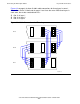
To change the numeric selector on the logic board:
1. Determine the fabric, zone, and layer for this switch. Refer to Plan the Fabric, Zone
Number, and Layer Number for Each 6780 Switch on page 3-11.
2. Using a pointed object, such as a straightened metal paper clip, press the “+”
below the digit to increment the number, or press the ” -” above the digit to
decrement the number.
3. Use the four-digit numeric selector to set the configuration for each switch as
follows:
•
For the first two digits, enter 96 for the X fabric or 97 for the Y fabric.
•
For the third digit, enter the zone number of 1, 2, or 3.
•
For the fourth digit, enter the layer number of 1, 2, 3, or 4.
Quantity Description
1 Cable-management assembly including tray, 2 vertical radius
guides (VRGs), and 13 cable-management cartridges
4 M6 Torx screws
1 Cable labels
4 Velcro ties for the fiber-optic cables
Note. If you are migrating from a star, split-star, or tri-star topology, set the numeric selector
so that the nodes connected to that switch continue to have the same ServerNet Node
numbers.
If you set the numeric selector after the switch is powered on, you must perform a hard reset
for the setting to take effect.
Note. Do not use a pencil. The pencil point could break and jam the numeric selector.
Note. The long-distance option requires different numeric selector settings. See
Appendix G, Using the Long-Distance Option
.