SL500 (M852x) Tape Library Installation and User’s Guide Abstract This manual describes how to install and use a SL500 tape library on HP NonStop Sseries servers, HP Integrity NonStop NS-series servers and HP NonStop BladeSystems. Product Version N.A. Supported Release Version Updates (RVUs) This publication supports J06.14 and all subsequent J-series RVUs, H06.25 and all subsequent H-series RVUs, and G06.31 and all subsequent G-series RVUs, until otherwise indicated by its replacement publication.
Document History Part Number Product Version Published 541531-004 N.A. February 2006 541531-005 N.A. June 2006 541531-006 N.A June 2007 541531-007 N.A. May 2008 541531-008 N.A.
SL500 (M852x) Tape Library Installation and User’s Guide Glossary Index What’s New in This Manual v Manual Information v New and Changed Information Examples Figures v 1.
. Cartridge Information Contents Entering a Cartridge Through the CAP 3-1 Powering On the Tape Library 3-3 Powering Off the Tape Library 3-3 Manual Mode 3-4 Opening the Front Door (Without Power) 3-4 Securing the Front Door (Without Power) 3-5 Locate and Remove Cartridge 3-6 Insert Cartridges Into Slots 3-6 Inserting a Cartridge Into a Tape Drive 3-8 Removing a Cartridge From a Tape Drive 3-9 Removing a Cartridge From the Gripper Assembly Replacing a Cleaning Cartridge 3-11 3-10 4.
A. Specifications Contents A. Specifications Tape Library Components Weights A-3 Tape Library Environment A-3 Power A-4 Power Cord Numbers and Receptacles Power Specifications A-7 SCSI Cables A-8 Fiber Cables A-8 A-4 B. Configuring the M8706A Tape Drive for the NonStop BladeSystem Server Configuration Overview B-1 Adding the Control Path B-1 Adding the Data Path B-2 Verify the Tape Configuration B-2 Troubleshoot the Tape Configuration B-3 Safety and Compliance Index Examples Figures Figure 1-1.
Tables Contents Figure 3-6. Figure 3-7. Figure 3-8. Figure 4-1. Figure 4-2. Figure 4-3. Figure 4-4. Figure A-1. Figure A-2. Figure A-3. Inserting Cartridge Into Tape Drive 3-8 Location of Unload Button 3-9 Manual Release Screw 3-11 Ultrium Cartridge Components 4-3 LTO Cartridge Labels 4-4 Ultrium Cartridge Label 4-5 Write-Protect Switch 4-6 Library and Rack Dimensions A-1 Tape Library and Rack Dimensions A-2 Power Cabling A-6 Tables Table 1-1. Table 1-2. Table 1-3. Table 1-4. Table 2-1. Table 4-1.
What’s New in This Manual Manual Information SL500 (M852x) Tape Library Installation and User’s Guide Abstract This manual describes how to install and use a SL500 tape library on HP NonStop Sseries servers, HP Integrity NonStop NS-series servers and HP NonStop BladeSystems. Product Version N.A. Supported Release Version Updates (RVUs) This publication supports J06.14 and all subsequent J-series RVUs, H06.25 and all subsequent H-series RVUs, and G06.
What’s New in This Manual New and Changed Information SL500 (M852x) Tape Library Installation and User’s Guide —541531-010 vi
1 Overview of the Tape Library This section includes: Views and Locations 1-4 Physical Configurations 1-4 Robotics Unit 1-11 Electronics 1-14 Fans 1-14 Power System 1-15 Cartridge Access Port 1-15 Supported Tape Drives 1-16 Audit of Tape Library 1-17 Safety Features 1-17 Interfaces 1-18 This section contains an overview of the major hardware components of the tape library.
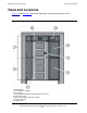
Overview of the Tape Library Views and Locations Views and Locations Figure 1-1 and Figure 1-2 show the tape library views and the locations of its components. Figure 1-1. Front View of Tape Library Components 1. Base Module 2. Drive Expansion Module 3. Library Door 4. Drive Expansion Module Cartridge Access Port (CAP) 5. Library Door Lock 6. Base Unit Cartridge Access Port (CAP). 7. Keypad Assembly. 8.
Overview of the Tape Library Views and Locations Figure 1-2. Back View of Tape Library Components 1. Base Module 2. Drive Expansion Module 3. Redundant Power Supply 4. Standard Power Supply 5. Library Power Switch 6. Tape Drive 1 in Base Unit 7.
Overview of the Tape Library Physical Configurations Physical Configurations Figure 1-3 on page 1-5 shows a tape library with only a base module. Figure 1-4 on page 1-6 shows a tape library with a base module that has nine reserved slots, one drive expansion module, and one cartridge expansion module. Figure 1-5 on page 1-7 shows a tape library with a base module that has two reserved slots, one drive expansion module, and one cartridge expansion module. Note.
Overview of the Tape Library Physical Configurations Figure 1-3.
Overview of the Tape Library Physical Configurations Figure 1-4.
Overview of the Tape Library Physical Configurations Figure 1-5.
Overview of the Tape Library Physical Configurations Figure 1-6.
Overview of the Tape Library Capacities Capacities Table 1-1 on page 1-10 shows the number of cartridge and tape drive slots available depending on the type and number of modules installed. Slot counts are based on the following assumptions: ! ! Capacity includes reserved slots for diagnostic and cleaning cartridges. ! The base module has a 5-slot CAP; the drive expansion module (DEM) and cartridge expansion module (CEM) each have two 5-slot CAPs.
Capacities Overview of the Tape Library Table 1-1.
Overview of the Tape Library Robotics Unit Robotics Unit The robotics unit provides movement of cartridges among the storage slots, tape drives, and cartridge access ports (CAPs). The three main robotic components are: ! ! ! Z drive assembly X table assembly Hand assembly The Z drive assembly uses the Z drive pulley to move the X table up and down to the desired slot or tape drive.
Overview of the Tape Library Figure 1-7. Robotics Components 1. Z drive assembly 2. Hand assembly 3. Keypad assembly 4.
Overview of the Tape Library Figure 1-8. Hand Assembly 1. Gripper 2. Bar-code scanner 3. Wrist hub 4.
Overview of the Tape Library Electronics Electronics The electronics consists of the control path and robotic cards in the base unit.
Power System Overview of the Tape Library Power System The base unit has one standard power supply. A second supply can be ordered and installed to provide redundant power to the module components. Each supply should be plugged into a separate circuit and powered on to provide redundant power. If one supply fails, the second supply automatically provides power.
Supported Tape Drives Overview of the Tape Library Supported Tape Drives The tape library can accommodate from 1 to 14 tape drives. The LTO generation 3 tape drives (N1523A and M8504) supports Ultrium 3 media, Ultrium 2 media, and Ultrium 1 media (read only). The LTO generation 4 tape drive (M8607A) supports Ultrium 4 media, Ultrium 3 media, and Ultrium 2 media (read only). Figure 1-9.
Overview of the Tape Library Audit of Tape Library Audit of Tape Library An audit is the method by which the tape library keeps track of all cartridge locations within the unit. An audit occurs when you: ! ! ! Power on the library Open and close the front door Close the CAP (CAP slots only) Initialization occurs when the tape library is powered on or when the front door is opened and closed. During initialization, the RLC card applies voltage to the motors (gripper, reach, wrist, and Z drive).
Overview of the Tape Library Interfaces Interfaces The major tape library interfaces are: ! ! ! Library control path support for HVD SCSI ! Environmental port for monitoring fans, tape drives, and power. This port is internal and cannot be accessed by the customer. ! ! Cartridge access ports and sensors for indicating a door open or closed condition. Ethernet port CLI serial port for local access for service representative, manufacturing and engineering (Not for customer use).
2 Controls and Indicators This section includes: Power Switch 2-1 Keypad 2-1 Power Switch When the switch is in position 1 the tape library and tape drives are powered on. When the switch is in position 0 the tape library and tape drives are powered off. Note. Earlier built tape libraries had power supplies that had individual power switches. Later tape libraries have one power switch that controls all power supplies in the rack.
Keypad Controls and Indicators Figure 2-1. Buttons and Indicators 1. Door Open button 2. Door Open LED 3. CAP Open button 4. CAP Open LED 5. Service Required LED 6. Library Active LED 7.
Keypad Controls and Indicators Table 2-1. Keypad Buttons and Indicators Buttons/Indicators Description Service Robot Indicator LED is lit when the robot is not functioning. Replace the robotics unit. Library Active Service Required Open Door Indicator ! ! LED is normally solid green. LED turns off when the tape library experiences a failure. If it never turns on, an initialization or power failure has occurred. Indicator ! ! LED is normally solid green.
Controls and Indicators SL500 (M852x) Tape Library Installation and User’s Guide —541531-010 2 -4 Keypad
3 Library Operation This section includes: Automated Mode 3-1 Manual Mode 3-4 Automated Mode Automated mode is the normal operating mode of the tape library. The controlling software instructs the hand assembly to move cartridges among the storage slots, tape drives, and cartridge access port (CAP) without operator intervention. Opening the Front Door (With Power) To open the front door when tape library power exists: 1. Press the Open Door button on the keypad. a.
Entering a Cartridge Through the CAP Library Operation 4. Place the cartridge into one of the magazine slots, making sure that the VOLID label is visible and the hub of the cartridge is down. 5. Grip the handle and slide the magazine back into the CAP. Figure 3-1. Sliding a Magazine Into a CAP 6. Close the CAP door making sure that the door is securely latched.
Powering On the Tape Library Library Operation Powering On the Tape Library To power on the library: 1. Close and lock the front door if the door is open. 2. Press the power switch (on the top right corner of the back of the library) to the ON (1) position. Powering Off the Tape Library Caution. If you power off the tape library without performing the following procedure, you risk possible equipment or cartridge damage or loss of data. 1. Make sure that all jobs have completed processing. 2.
Manual Mode Library Operation Manual Mode This section describes the operation of the tape library in manual mode. Manual mode occurs then the tape library is taken offline, or loses power, or the front door is opened. Opening the Front Door (Without Power) To open the front door when no tape library power exists: Note. You must manually move the robotics park lever (beneath the facade and to the bottom left of the keypad) to the left position so that you can open the door with the key.
Securing the Front Door (Without Power) Library Operation WARNING. Possible injury to finger: Make sure that your finger is completely to the left in the next step so that it will not be pinched when the door locking lever extends as shown in the lower picture. Figure 3-3. Door Locking Lever Extended 3. While using one hand to move the robotics park lever to the left, use your other hand to unlock the door with the key.
Locate and Remove Cartridge Library Operation Figure 3-4. Moving Robotics Park Lever 3. While still holding the door shut, release the robotics park lever. 4. Use the key to lock the door. The robotics lever automatically moves to the right when the door locking lever retracts. Locate and Remove Cartridge To locate a particular cartridge inside the tape library: 1. Open the door. 2. Locate the particular cartridge by its VOLID (volume ID) label and slot. 3.
Insert Cartridges Into Slots Library Operation Figure 3-5. Inserting Cartridges Into Slots 1. Wall of arrays slots 2.
Inserting a Cartridge Into a Tape Drive Library Operation Inserting a Cartridge Into a Tape Drive To manually insert a cartridge into a tape drive: 1. Obtain the VOLID label, location, and tape drive number from the server console. 2. Open the door. 3. Locate the cartridge. Caution. Potential equipment damage. You must insert the cartridge properly or you will damage the tape drive. 4. Hold the cartridge so that the VOLID is facing you and can be read from right to left. 5.
Removing a Cartridge From a Tape Drive Library Operation Removing a Cartridge From a Tape Drive To manually remove a cartridge from a tape drive: 1. Open the door and locate the appropriate tape drive. Caution. Possible data loss. Failure to perform and wait approximately 12 seconds until the operation completes. 2. Press the Unload button on the tape drive and wait approximately 12 seconds until the operation completes. Figure 3-7. Location of Unload Button 3.
Removing a Cartridge From the Gripper Assembly Library Operation Removing a Cartridge From the Gripper Assembly The hand assembly can be in any position when the tape library loses power. Before you can remove the cartridge, the hand assembly must be facing the front left arrays and aligned with an empty slot. If the hand assembly is facing right: 1. Gently turn the hand to the left. 2. Slide the hand assembly along the rail until the gripper is positioned across from an empty slot and close to you. 3.
Replacing a Cleaning Cartridge Library Operation Figure 3-8. Manual Release Screw 1. Gripper belt and pulleys 2. Gripper 3. Release screw Replacing a Cleaning Cartridge Cleaning cartridges have a limited life span. When the usage count exceeds its limit, you must replace it with a new one. To replace a cleaning cartridge: 1. Open the door. 2. Remove the expired cleaning cartridge from its reserved slot. 3. Insert the new cleaning cartridge into that slot. 4. Close the tape library door. 5.
Library Operation Replacing a Cleaning Cartridge SL500 (M852x) Tape Library Installation and User’s Guide —541531-010 3- 12
4 Cartridge Information This section includes: Handle Cartridges 4-1 Inspect Cartridges 4-1 Maintain Cartridges 4-2 Ultrium Cartridges 4-3 Handle Cartridges Improper handling of cartridges can result in loss of data or damage to a tape library component. To handle a cartridge correctly: ! ! ! Make sure the leader is latched every time you pick up a cartridge. ! ! ! ! ! Never pull tape from a cartridge. Keep cartridges clean.
Cartridge Information Maintain Cartridges Maintain Cartridges It is important to keep your tape cartridges in good condition. A defective or dirty cartridge can damage a tape drive. When you store a cartridge: ! ! Leave it in its protective wrapping until you are ready to use it. ! Make sure the cartridge has been in its operating environment for at least 24 hours. Choose a clean environment that duplicates the conditions of the room in which it is used. When you clean a cartridge exterior: Caution.
Cartridge Information Ultrium Cartridges Ultrium Cartridges Figure 4-1. Ultrium Cartridge Components 1. Write-protect switch (data cartridge has red switch, cleaning cartridge has gray switch) 2. Volume ID label (barcode to hub side of cartridge) 3. Access door 4. Leader pin Apply Cartridge Labels Cartridge labels reflect the cartridge media and usage. If your cartridges were not ordered with labels already applied, you must apply them yourself.
Valid Labels Cartridge Information Table 4-1. LTO Cartridge Codes Label Type of Cartridge CLN plus C1 Cleaning cartridge for tape drives CLN plus CU Universal cleaning cartridge DG plus L Diagnostic cartridge (Apply a DG label to a blank data cartridge to be used for diagnostic tests.) L1 Generation 1 data cartridge L2 Generation 2 data cartridge L3 Generation 3 data cartridge L4 Generation 4 data cartridge L5 Generation 5 data cartridge Figure 4-2.
Cartridge Information Valid Labels When an audit occurs the tapes in the tape drives are not audited. Unlabeled cartridges are not supported and will not be recognized by an audit. Perform these steps before applying the label into the recessed area on the cartridge: 1. Make sure the cartridge has been at room temperature for at least 24 hours. 2. Clean the surface where the labels will be placed using a cleaning solution made for this purpose. 3. Locate the type of label that you require. 4.
Cartridge Information Setting the Write-Protect Switch Setting the Write-Protect Switch You can set the write-protect switch so the cartridge is write enabled. To write-enable the tapes, slide the switch to reveal the open lock symbol. In this position, the tape drive can write as will as read data. This setting is recommended when inserting cartridges into the tape library. You can set the write-protect switch so that the cartridge is read only. Slide the switch to reveal the symbol of a closed lock.
Setting the Write-Protect Switch Cartridge Information Table 4-2. LTO Gen 3, Gen 2, and Gen 1 Cartridge Specifications Specification L3 Cartridge L2 Cartridge L1 Cartridge Capacity, native (uncompressed) 400 GB 200 GB 100 GB Capacity (compressed) 800 GB 400 GB 200 GB Search and rewind speed 7 m/s 7 m/s 7 m/s Archival life 15–30 years 15-30 years 15-30 years Number of tracks 704 tracks 512 tracks 384 tracks Table 4-3.
Cartridge Information Setting the Write-Protect Switch SL500 (M852x) Tape Library Installation and User’s Guide —541531-010 4 -8
5 Configuring the M8520 Tape Library for the NonStop S-Series Server The section covers: Supported Connections 5-1 Adding the Control Path and the Data Path 5-1 Supported Connections You can attach the M8520 tape library (control path and data path) to a NonStop S-series server using one of the following: ! ! ! ServerNet/DA IOMF CRU PMF CRU Note. The control path is used to control the robot and the data path is used to control the tape drive or drives.
Configuring the M8520 Tape Library for the NonStop S-Series Server PMF CRU To add the data path: -> SCF -> ADD TAPE $N1523A, SENDTO STORAGE, LOCATION (1,1,55), SAC 1, DEVICEID 5, PRIMARYCPU 0, BACKUPCPU 1 -> START TAPE $N1523A -> STATUS TAPE $N1523A, DETAIL For complete details about the ADD and STATUS commands, including command syntax, see the SCF Reference Manual for the Storage Subsystem. PMF CRU To add the control path to the server configuration database, use the SCF ADD SCSI command.
6 Configuring the M8521/M8521A Tape Library for the Integrity NonStop NS-Series Server The section covers: Supported Connection 6-1 Adding the Control Path and Data Path 6-1 Supported Connection You can attach the M8521/M8521A tape library (control path and data path) to a Fibre Channel ServerNet adapter (FCSA) on an Integrity NonStop NS-series server. Note. The control path is used to control the robot, and the data path is used to control the tape drive or drives.
Configuring the M8521/M8521A Tape Library for the Integrity NonStop NS-Series Server Adding the Control Path and Data Path To add the data path: 1. In SCF, issue this command: SCF> ADD TAPE $tape, SENDTO STORAGE, LOCATION (group, module, slot), SAC sac-id, PORTNAME 64-bit-portname, LUN lun-id Example: SCF> ADD TAPE $M8504, SENDTO STORAGE, LOCATION (110,2,2), SAC 2, LUN 0, PORT 50060B00002E69CD Note.
7 Configuring the M8521 Tape Library for the NonStop S-Series Server The section covers: Configuration Overview 7-1 Adding the Control Path and Data Path 7-1 Configuration Overview You can attach the tape library (control path and data path) to a NonStop S-series server via an IOAM enclosure. The tape library attaches to the FCSA (Fibre Channel ServerNet adapter) in the IOAM enclosure.
Configuring the M8521 Tape Library for the NonStop S-Series Server Adding the Control Path and Data Path To add the data path: 1. In SCF, issue this command: SCF> ADD TAPE $tape, SENDTO STORAGE, LOCATION (group, module, slot), SAC sac-id, PORTNAME 64-bit-portname, LUN lun-id Example: SCF> ADD TAPE $M8504, SENDTO STORAGE, LOCATION (110,2,2), SAC 2, LUN 0, PORT 50060B00002E69CD Note. The LUN (logical unit number) for all Fibre Channel tape storage devices directly attached to the IOAM enclosure is 0. 2.
A Specifications The next pages provide tape library, tape drive, and cartridge specifications. Figure A-1. Library and Rack Dimensions 1. 48.3 cm (19.0 in.) width of front of base module with flange 2. 35.6 cm (14.0 in.) height of base module 3. 35.6 cm (14.0 in.) height of expansion module 4. 46.5 cm (18.3 in.) distance between rack holes 5. 60.9 cm (24.0 in.) to 86.4 cm (34.0 in.), optimally 74 cm (29 in.) front to rear rack mounting distance 6. 44.5 cm (17.5 in.
Specifications Figure A-2. Tape Library and Rack Dimensions 1. 60.9 cm (2 ft) minimum service clearance behind the library or rack 2. 81.0 cm (31.9 in.) depth of base module from front mounting plane to back of tape drives 3. 76.2 cm (30.0 in.) depth of base module 4. 3.8 cm (1.5 in.) depth of front door, required clearance 5. 5.3 cm (2.1 in.) depth of front door and unique latch hardware 6. 5.9 cm (2.3 in.) key depth 7. 24.1 cm (9.5 in.) front door opening clearance 8. 60.
Tape Library Components Weights Specifications Tape Library Components Weights This table lists the weights of the tape library, tape drives and trays, and cartridges. Table A-1. Library Component Weights Components Weight Base module with 1 power supply, 2 tape drives, and robotics unit 98 pounds (44.5 kilograms) Drive expansion module (DEM) with 1 power supply and 4 tape drives 91 pounds (41.3 kilograms) Cartridge expansion module (CEM) 44.2 pounds (20.1 kilograms) Robotics unit 22.
Power Specifications Power Note. The tape library is offered with redundant power in all the modules that have power supplies in them. The power cords are shipped with the unit and are selected to match the geographical power requirements of that area. Power Cord Numbers and Receptacles Power cord part numbers are listed by country in the following table. All cords are 3 meters (9.81 feet). Table A-3. Power Cord and Receptacles Input Voltage Country Part Number Receptacle Type 100 to 127 VAC U.S.
Power Cord Numbers and Receptacles Specifications Installing the Power Cords WARNING. Possible bodily harm and equipment damage: The power cord must not be plugged in until the supply has been properly installed. If your rack has a power distribution unit (PDU), plug each power cable from the power supply receptacle to the PDU, and then plug the PDU cable to the wall receptacle. If your rack does not have a PDU, plug each power cable from the power supply receptacle to the wall receptacle.
Power Cord Numbers and Receptacles Specifications Figure A-3. Power Cabling 1 2 3 1. To wall outlet or external power strip 2. To rack PDU, if present 3.
Power Specifications Specifications Power Specifications These tables list power specifications for the modules and tape drives. Table A-5. Power for Library Without Tape Drives Input voltage 100-240 VAC, single phase Frequency 50/50 Hz Maximum library power consumption 1.4 A @ 120 V 0.8 A @ 240 V Maximum heat output 614 Btu/hr Voltage-amperes 180 VA Table A-6.
SCSI Cables Specifications SCSI Cables Part Number Description 542497-001 3 meter copper SCSI cable 542498-001 15 meter copper SCSI cable 542499-001 20 meter copper SCSI cable 542500-001 23 meter copper SCSI cable Fiber Cables Connector Fiber Cable Fiber Cable Distance LC-LC 50/125 µm 2-300 meters (6.56-984.25 feet) LC-LC 62.5/125 µm 3-150 meters (9.84-492.13 feet) Table A-8.
B Configuring the M8706A Tape Drive for the NonStop BladeSystem Server This section covers: Configuration Overview B-1 Adding the Control Path B-1 Adding the Data Path B-2 Verify the Tape Configuration B-2 Troubleshoot the Tape Configuration B-3 Configuration Overview NonStop BladeSystems can connect to the tape drive by means of a CLIM (CLuster I/O Module), Each CLIM provides access to the tape drive through a Fibre Channel port.
Adding the Data Path Configuring the M8706A Tape Drive for the NonStop BladeSystem Server Adding the Data Path Issue an SCF ADD TAPE command to configure the tape drive. This is an example: -> ADD TAPE $M8706A, SENDTO STORAGE, CLIM C1002531, LUN 1 You can specify backup and primary CPUs if you need to balance the processing load to other CPUs.
Configuring the M8706A Tape Drive for the NonStop BladeSystem Server Troubleshoot the Tape Configuration Troubleshoot the Tape Configuration ! ! Check that the processes on the CLIM are running and if they are not, start them. If either of these conditions occur: " The SCF STATUS CLIM $ZZCIP.
Configuring the M8706A Tape Drive for the NonStop BladeSystem Server Troubleshoot the Tape Configuration SL500 (M852x) Tape Library Installation and User’s Guide —541531-010 B- 4
Safety and Compliance This section contains three types of required safety and compliance statements: ! ! ! Regulatory compliance Waste Electrical and Electronic Equipment (WEEE) Safety Regulatory Compliance Statements The following regulatory compliance statements apply to the products documented by this manual. FCC Compliance This equipment has been tested and found to comply with the limits for a Class A digital device, pursuant to part 15 of the FCC Rules.
Safety and Compliance Regulatory Compliance Statements Korea MIC Compliance Taiwan (BSMI) Compliance Japan (VCCI) Compliance This is a Class A product based on the standard or the Voluntary Control Council for Interference by Information Technology Equipment (VCCI). If this equipment is used in a domestic environment, radio disturbance may occur, in which case the user may be required to take corrective actions.
Regulatory Compliance Statements Safety and Compliance European Union Notice Products with the CE Marking comply with both the EMC Directive (89/336/EEC) and the Low Voltage Directive (73/23/EEC) issued by the Commission of the European Community.
SAFETY CAUTION Safety and Compliance SAFETY CAUTION The following icon or caution statements may be placed on equipment to indicate the presence of potentially hazardous conditions: DUAL POWER CORDS CAUTION: “THIS UNIT HAS MORE THAN ONE POWER SUPPLY CORD. DISCONNECT ALL POWER SUPPLY CORDS TO COMPLETELY REMOVE POWER FROM THIS UNIT." "ATTENTION: CET APPAREIL COMPORTE PLUS D'UN CORDON D'ALIMENTATION. DÉBRANCHER TOUS LES CORDONS D'ALIMENTATION AFIN DE COUPER COMPLÈTEMENT L'ALIMENTATION DE CET ÉQUIPEMENT".
Safety and Compliance Waste Electrical and Electronic Equipment (WEEE) HIGH LEAKAGE CURRENT To reduce the risk of electric shock due to high leakage currents, a reliable grounded (earthed) connection should be checked before servicing the power distribution unit (PDU).
Safety and Compliance Safety Safety Safety information can be accessed from the left navigation area of the NTL home page: select NonStop Computing>Important Safety Information. A document window containing a binder of safety information, in several languages, appears. In the document window, click a document title to open the safety information in another language. Local HP support can also help direct you to your safety information.
Index A S Automated mode 3-1 SCF ADD TAPE command for NonStop BladeSystems B-2 Specifications A-1 C Cartridge applying labels 4-3 handling 4-1 information 4-1 inspecting 4-1 LTO codes 4-4 maintaining 4-2 manually inserting 3-8 removing 3-9 removing from gripper assembly 3-10 ultrium 4-3 write protect switch 4-6 Cleaning cartridge replacing 3-11 Configuration 5-1 nonstop ns-series 6-1 nonstop s-series 5-1, 7-1 T Tape library audit 1-17 capacities 1-9 cartridge access port 1-15 electronics 1-14 fans 1-14
T Index SL500 (M852x) Tape Library Installation and User’s Guide —541531-010 Index -2