
SL500 (M852x) Tape Library Installation and User's Guide (G06.31+, H06.11+, J06.03+)


Contents
SL500 (M852x) Tape Library Installation and User’s Guide—541531-010
iii
A. Specifications
A. Specifications
Tape Library Components Weights A-3
Tape Library Environment A-3
Power A-4
Power Cord Numbers and Receptacles A-4
Power Specifications A-7
SCSI Cables A-8
Fiber Cables A-8
B. Configuring the M8706A Tape Drive for the NonStop
BladeSystem Server
Configuration Overview B-1
Adding the Control Path B-1
Adding the Data Path B-2
Verify the Tape Configuration B-2
Troubleshoot the Tape Configuration B-3
Safety and Compliance
Index
Examples
Figures
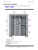
Figure 1-1. Front View of Tape Library Components 1-2
Figure 1-2. Back View of Tape Library Components 1-3
Figure 1-3. Base Module Slots 1-5
Figure 1-4. Slots Locations for Firmware Slot Mapping 1-6
Figure 1-5.
Slots Locations for SCSI Element Numbering Mapping 1-7
Figure 1-6. Slot Capacity for Back Wall of Cartridge Expansion Module 1-8
Figure 1-7.
Robotics Components 1-12
Figure 1-8.
Hand Assembly 1-13
Figure 1-9.
Supported Tape Drives 1-16
Figure 1-10. Tape Library Interfaces Locations 1-18
Figure 2-1. Buttons and Indicators 2-2
Figure 3-1.
Sliding a Magazine Into a CAP 3-2
Figure 3-2.
Lever Not in Parked Position 3-4
Figure 3-3. Door Locking Lever Extended 3-5
Figure 3-4. Moving Robotics Park Lever 3-6
Figure 3-5. Inserting Cartridges Into Slots 3-7