
SL500 (M852x) Tape Library Installation and User's Guide (G06.31+, H06.11+, J06.03+)


Contents
SL500 (M852x) Tape Library Installation and User’s Guide—541531-010
iv
Tables
Figure 3-6. Inserting Cartridge Into Tape Drive 3-8
Figure 3-7. Location of Unload Button 3-9
Figure 3-8. Manual Release Screw 3-11
Figure 4-1. Ultrium Cartridge Components 4-3
Figure 4-2. LTO Cartridge Labels 4-4
Figure 4-3. Ultrium Cartridge Label 4-5
Figure 4-4. Write-Protect Switch 4-6
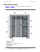
Figure A-1. Library and Rack Dimensions A-1
Figure A-2. Tape Library and Rack Dimensions A-2
Figure A-3. Power Cabling A-6
Tables
Table 1-1. Cartridge Slot and Tape Drive Capacities 1-10
Table 1-2.
LTO Generation 3 Specifications 1-16
Table 1-3. LTO Generation 4 Specifications 1-16
Table 1-4. LTO Generation 5 Specifications 1-16
Table 2-1. Keypad Buttons and Indicators 2-3
Table 4-1. LTO Cartridge Codes 4-4
Table 4-2. LTO Gen 3, Gen 2, and Gen 1 Cartridge Specifications 4-7
Table 4-3. LTO Gen 5 and Gen 4 Cartridge Specifications 4-7
Table A-1. Library Component Weights A-3
Table A-2. Library Environment Specifications A-3
Table A-3. Power Cord and Receptacles A-4
Table A-4. Non-Country-Specific Cords A-4
Table A-5. Power for Library Without Tape Drives A-7
Table A-6. Power for Base Unit and Two LTO Tape Drives A-7
Table A-7. Power for Drive Expansion Module and Four LTO Tape Drives A-7
Table A-8.
LC - LC Multi-Mode Fiber 50/125 A-8