
SNAX/APN Application Programming Manual

The CRT Interface
SNAX/APN Application Programming Manual—420111-001
2-4
The Change Direction Indicator
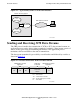
2. The second read operation is initiated by a READ procedure call; for example:
CALL READ (filenum, buffer, countbuffer);
This call reads the incoming data block into the second parameter, buffer. The
third parameter, countbuffer, specifies the size of the incoming data block; this
value is obtained by the WRITEREAD procedure call in Step 1.
For more information on how to use the WRITEREAD and READ procedure calls, see
the Guardian Procedure Calls Reference Manual.
The Change Direction Indicator
Communication between the application process and device is in half-duplex mode; that
is, data can be transmitted in only one direction at a time. When the application has
finished sending data and is prepared to receive data from a terminal device, it must
signal the device, which then becomes the sending unit. This is accomplished by the
Change Direction Indicator (CDI), which is managed by the CRT protocol.
Changing the SETMODE function 163 or configuring CDI using SCF or SPI allows you
to specify whether the CDI is sent in the same outbound data stream or in a separate RU.
Sending the CDI in the same data stream reduces time delay by eliminating the flow of
an extra RU. IF the destination LU is a terminal, sending the CDI in the same data
stream allows faster keyboard access.
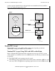
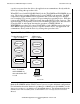
The CDI is found in the SNA request/response header (RH), one of the various SNA
headers preceding the 3270 data stream (see Figure 2-2
). This subsection describes the
three modes for enabling CDI:
•
Normal CDI mode, which can be enabled by setting SETMODE function 163 to
(SETMODE 163,0). This mode specifies that the CDI is generated when an
application in the send state issues a READ procedure call, or when an application
issues a WRITE procedure call to send an outbound data stream to the device, and
the 3270 commands are read commands (i.e. READ, READ MODIFIED, and
READ MODIFIED ALL). In the latter case, the CDI is sent on a null RU.
•
Enhanced CDI mode, which can be enabled by setting SETMODE function 163 to
(SETMODE 163,1). This mode specifies that the CDI is to be sent with the
outbound data when keyboard restore is indicated in bit 6 of the 3270 write control
character (WCC) field. Enhanced CDI mode operates the same as normal CDI
mode, except that when keyboard restore is indicated, the sender is requesting to be
placed in the receive state to allow the receiver to send.
•
Special CDI mode, which can be enabled by setting SETMODE function 163 to
(SETMODE 163,2). This mode specifies that WRITEREAD is supported, and that
the CDI can be sent when an application issues a WRITEREAD procedure call.
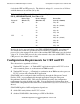
Table 2-1
, at the end of this subsection, summarizes the differences between the three
CDI modes.
For information on setting and switching CDI modes, refer to “Setting CDI Options
(SETMODE Function 163)” in the subsection “Functions Available With the CRT
Protocol,” later in this section.