
SNAX/XF and SNAX/APN Configuration and Management Manual

Configuring for Token-Ring Support
SNAX/XF and SNAX/APN Configuration and Management Manual—425836-006
9-6
The Architecture of Token-Ring Networks
The Architecture of Token-Ring Networks
A Token-Ring network is a type of local area network suitable for high-speed
interconnection of computers and computer-controlled devices over moderate
distances. The actual distance depends on cable type and line drivers.
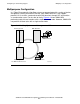
A Token-Ring LAN is a star-wired ring in which each station is attached to a nearby
concentrator. The electrical effect of the cables and concentrators creates a logical ring
between stations. The operation of the ring depends on each station retransmitting
data from its receive pair of cables to its transmit pair, regardless of whether that
station is involved in the data traffic. To ensure that the ring operates even when an
individual station is not operational, each station is required to maintain a DC voltage
on the cable connecting it to the concentrator. If power to the station fails, or the cable
is disconnected, the concentrator causes the ring to bypass that station.
The architecture of the Token-Ring LAN is defined in practice by implementations
primarily from IBM and Texas Instruments, and in principle by ANSI/IEEE standard
802.5 and ISO/DIS standard 8802/5. Most implementations of the Token-Ring also use
at least a part of the standardized Logical Link Control protocol (LLC) defined as
ANSI/IEEE standard 802.2 and ISO/DIS standard 8802/2.
Token Control of the Ring
The ability to send or receive data is restricted, based upon a 3-byte token that is
constantly flowing around the ring. Any station attached to the ring can send data to
another attached station when it receives the token and the token is “free.” To send
data, the token is captured, a field in the data frame is marked as “busy,” the
destination and source addressing information is filled in, data is added, and the frame
is transmitted onto the ring.
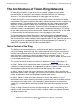
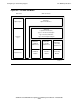
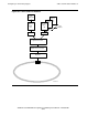
This access control to the physical medium is depicted in Figure 9-5 on page 9-7.
In Step 1, Station A has acquired the token, marked the field in a data frame as busy
(shown as the black rectangle), and appended an address (Station C) and some data.
A detailed description of the data frame can be found later in this section.
In Step 2, Station B reads the frame, determines that the token is busy and that the
destination address does not apply, and so passes the frame on around the ring. (Each
station also performs error checking before repeating the frame.)
In Step 3, Station C reads the frame, determines that its own address is in the
destination frame, copies the data into memory, and transmits the frame back onto the
ring. Note that the token field is still marked busy (black) because the originating
station (A) is responsible for removing the data frame from the ring when the frame
returns.
Finally, in Step 4, Station A receives the data frame and strips it from the ring, and
replaces it with a free token (shown in white). Another station may capture the token
and begin transmission.