
SNAX/XF and SNAX/APN Configuration and Management Manual

Configuring for Token-Ring Support
SNAX/XF and SNAX/APN Configuration and Management Manual—425836-006
9-14
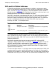
SAPs and Link Station Addresses
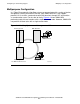
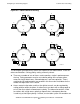
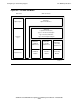
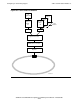
Figure 9-9 shows three stations (A, B, and C) connected on a Token-Ring. Station A
has SAP A1 that is connected to SAP B1 of Station B. Station B has three active SAPs.
SAP B2 has two connections, one with SAP C1 and one with SAP C2. SAP B3 is also
connected to SAP C1.
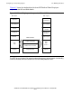
What Figure 9-9 does not show is multiple connections between the same two MAC
SAPs. For example, SAP B2 cannot have two sessions with SAP C1. The inability of
the same two MAC SAPs to have multiple connections is an architected rule of Token-
Ring, because there is no way to identify an application’s conversation to the lower
layers other than the unique combination of MAC SAP to MAC SAP connection.
The link station serves approximately the same function as an SNA physical unit (PU).
The upper layers of SNA may be running parallel sessions within a single LU or
supporting multiple sessions, but all these conversations are channeled through the
same PU. In SNA the architected restriction is 254 LUs per PU.
For a further discussion about SAPs, see Figure 9-13
on page 9-22 and Unique
Addressing on page 9-21.
Figure 9-9. SAPs and LLC Connections
A1
Station A
Station B Station C
SAP
LLC
MAC
B1 B3 C2B2 C1
VST909.vsd