SWAN Concentrator Installation and Support Guide Abstract This guide describes how to install and maintain the ServerNet wide area network (SWAN) concentrator on HP Integrity NonStop™BladeSystems, HP Integrity NonStop NS-series systems, and HP NonStop S-series systems. It is written for anyone who installs or maintains the SWAN concentrator. Product Version NA Supported Release Version Updates (RVUs) This manual supports G06.22 and all subsequent G-series RVUs, H06.
Document History Part Number Product Version Published 429391-002 NA December 2003 429391-003 NA April 2004 429391-004 NA August 2005 429391-005 NA April 2006 429391-006 NA August 2010
SWAN Concentrator Installation and Support Guide Glossary Index What’s New in This Guide vii Guide Information vii New and Changed Information Examples Figures Tables vii About This Guide ix Who Should Use This Guide ix How This Guide Is Organized ix Related Manuals x Notation Conventions x 1.
2. Installing a SWAN Concentrator (continued) Contents 2. Installing a SWAN Concentrator (continued) Removing a SWAN Concentrator 2-27 Replacing a SWAN Concentrator 2-29 Updating the SWAN Kernel Firmware 2-32 3. Using OSM to Update SWAN CLIP Firmware Using the Multi-Resources Actions Dialog Box 3-1 Step 1: Stop the SWAN Concentrator and CLIPs 3-2 Step 2: Check the Location and Version of the SWAN Firmware Step 3: Initiate the Firmware Update 3-3 Step 4: Start the SWAN Concentrator and CLIPs 3-5 3-3 4.
B. Cable Specifications Contents B. Cable Specifications Ethernet (RJ-45) Connector Signal Descriptions B-1 Pinouts of Supported WAN Signals B-2 Pinouts of Supported RS-232 Signals B-3 Pinouts of Supported RS-449 Signals B-5 Pinouts of Supported X.21 Signals B-7 Pinouts of Supported V.35 Signals B-9 Unsupported WAN Signals B-12 WAN Interface Converter Cable Wiring B-13 RS-232 Interface Converter Cable Wiring B-16 RS-449 Interface Converter Cable Wiring B-17 X.21 Interface Converter Cable Wiring B-18 V.
Examples (continued) Contents Examples (continued) Example A-5. Example A-6. Starting DLC TASK Objects Starting WAN Lines A-4 A-4 Figures Figure 1-1. Figure 1-2. Figure 1-3. Figure 1-4. Figure 2-1. Figure 2-2. Figure 2-3. Figure 2-4. Figure 2-5. Figure 2-6. Figure 2-7. Figure 2-8. Figure 2-9. Figure 2-10. Figure 2-11. Figure 2-12. Figure 2-13. Figure 2-14. Figure 2-15. Figure B-1. Figure B-2. Figure B-3. Figure B-4. Figure B-5. Figure B-6. Figure B-7. Figure B-8. Figure B-9. Figure C-1. Figure C-2.
Tables Contents Tables Table 1-1. Table 2-1. Table 2-2. Table 2-3. Table A-1. Table B-1. Table B-2. Table B-3. Table B-4. Table B-5. Table B-6. Table B-7. Table B-8. Table B-9. Table B-10. Table B-11. Table B-12.
Tables Contents SWAN Concentrator Installation and Support Guide —429391-006 vi
What’s New in This Guide Guide Information SWAN Concentrator Installation and Support Guide Abstract This guide describes how to install and maintain the ServerNet wide area network (SWAN) concentrator on HP Integrity NonStop™BladeSystems, HP Integrity NonStop NS-series systems, and HP NonStop S-series systems. It is written for anyone who installs or maintains the SWAN concentrator. Product Version NA Supported Release Version Updates (RVUs) This manual supports G06.
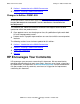
What’s New in This Guide • • Changes in Edition 429391-005 Section 1, Introduction to the SWAN Concentrator Section 2, Installing a SWAN Concentrator Changes in Edition 429391-005 Note. In April 2006, removed part numbers from Section 2, Installing a SWAN Concentrator. To view part numbers, from the home page of the NonStop Technical Library (NTL), select HP Integrity NonStop Service Information > Service Information > Part Numbers for NonStop Servers.
About This Guide The SWAN Concentrator Installation and Support Guide describes how to install and maintain a ServerNet wide area network (SWAN) concentrator on HP Integrity NonStop BladeSystems, HP Integrity NonStop NS-series, or HP NonStop S-series systems. This guide includes the following: • • • • Step-by-step instructions for installing, removing, and replacing a SWAN concentrator. Procedures for diagnosing problems.
Related Manuals About This Guide Table i. Contents Section or Appendix Title Contents A Diagnosing and Correcting SWAN Concentrator Problems Provides troubleshooting information for SWAN concentrator problems and firmware update issues. B Cable Specifications Describes the supported electrical signals and the wiring of cables and connectors provided by HP for use with the SWAN concentrator.
General Syntax Notation About This Guide UPPERCASE LETTERS. Uppercase letters indicate keywords and reserved words; enter these items exactly as shown. Items not enclosed in brackets are required. For example: MAXATTACH lowercase italic letters. Lowercase italic letters indicate variable items that you supply. Items not enclosed in brackets are required. For example: file-name [ ] Brackets. Brackets enclose optional syntax items. For example: TERM [\system-name.
General Syntax Notation About This Guide Punctuation. Parentheses, commas, semicolons, and other symbols not previously described must be entered as shown. For example: error := NEXTFILENAME ( file-name ) ; LISTOPENS SU $process-name.#su-name Quotation marks around a symbol such as a bracket or brace indicate the symbol is a required character that you must enter as shown. For example: "[" repetition-constant-list "]" Item Spacing.
Notation for Messages About This Guide !o:i. In procedure calls, the !o:i notation follows an output buffer parameter that has a corresponding input parameter specifying the maximum length of the output buffer in bytes. For example: error := FILE_GETINFO_ ( filenum , [ filename:maxlen ] ) ; !i !o:i Notation for Messages The following list summarizes the notation conventions for the presentation of displayed messages in this manual. Bold Text.
Change Bar Notation About This Guide either vertically, with aligned braces on each side of the list, or horizontally, enclosed in a pair of braces and separated by vertical lines. For example: obj-type obj-name state changed to state, caused by { Object | Operator | Service } process-name State changed from old-objstate to objstate { Operator Request. } { Unknown. } | Vertical Line. A vertical line separates alternatives in a horizontal list that is enclosed in brackets or braces.
1 Introduction to the SWAN Concentrator This section provides a high-level overview of the architecture and components of the ServerNet wide area network (SWAN) concentrator. Topics described in this section include: • • • • SWAN Concentrator Features SWAN Concentrator Connections on page 1-4 WAN Ports and Communications Line Interface Processors (CLIPs) on page 1-8 SWAN Firmware File on page 1-9 Note.
Power Requirements Introduction to the SWAN Concentrator Power Requirements The SWAN concentrator power requirements are located on the physical label on the SWAN concentrator as shown in Figure 1-1. CLIP 1 B 2 A B LA: 08008EXXXXXX A LA: 08008EXXXXXX HI-POT B LA: 08008EXXXXXX 100-240VAC, 50/60 HZ, IA LA: 08008EXXXXXX PWA:106523XXX-XX TC XXXXXX MODEL T/3880 ASM: 114645XXX-XX XXXXXX A LA: 08008EXXXXXX PATH LA: 08008EXXXXXX Figure 1-1.
Introduction to the SWAN Concentrator Protocols and Line Speeds Protocols and Line Speeds A SWAN concentrator can support various line speeds based on the protocol used. The maximum line speeds for the protocols supported by the SWAN concentrator are as follows: Asynchronous For asynchronous communications, the maximum line speed is 19.2 kb/s Byte-synchronous For Envoy byte-synchronous communications software, the maximum line speed is 9,600 kb/s (using both lines on the CLIP) or 19.
Introduction to the SWAN Concentrator SWAN Concentrator Connections SWAN Concentrator Connections SWAN concentrator connections provide redundant ServerNet X and Y fabrics to the Ethernet adapters. If one ServerNet fabric fails, the Ethernet adapter can still be accessed using the remaining ServerNet fabric. HP recommends configuring a SWAN concentrator to connect to the Ethernet ports on two E4SAs, FESAs, GESAs, or G4SAs.
Introduction to the SWAN Concentrator SWAN Concentrator Configuration Limits information about this configuration, see the Introduction to Networking for HP Integrity NonStop NS-Series Servers or the NonStop NS-Series Planning Guide. SWAN Concentrator Configuration Limits As of the G06.07 release, the previous limit of 100 SWAN concentrators on each system no longer applies. Now, a maximum of 3600 concentrators (of any entity type) can be configured through the SCF interface.
Introduction to the SWAN Concentrator Ethernet Ports on the SWAN Concentrator Figure 1-2.
Introduction to the SWAN Concentrator Ethernet Ports on the SWAN Concentrator Figure 1-3 shows how the SWAN concentrator connects to the Ethernet ports on the NonStop S-series system. A SWAN concentrator can also connect to a LAN adapter (such as the E4SA) that is installed in a NonStop S-series I/O enclosure and which connects to an Integrity NonStop NS-series system, as long as the NonStop S-series I/O enclosure has IOMF 2 components installed. Figure 1-3.
Introduction to the SWAN Concentrator Ethernet Ports on the SWAN Concentrator WAN Ports and Communications Line Interface Processors (CLIPs) Three CLIPs are provided on a SWAN concentrator. Each CLIP has two WAN ports that can run different communications protocols or electrical interfaces simultaneously. For enhanced reliability, each CLIP has access to both Ethernet ports. Figure 1-4 shows the six WAN ports on the front panel of the SWAN concentrator.
Introduction to the SWAN Concentrator SWAN Firmware File SWAN Firmware File The SWAN firmware file is the 510 disk file that resides on a NonStop system disk file and is downloaded to the SWAN concentrator. The SWAN firmware file contains the following: • • SWAN Bootcode (T7954), which is written into the flash programmable memory (PROM) on each CLIP on the SWAN concentrator.
Introduction to the SWAN Concentrator SWAN Concentrator Installation and Support Guide—429391-006 1- 10 SWAN Firmware File
2 Installing a SWAN Concentrator This section describes how to install, remove, and replace a ServerNet wide area network (SWAN) concentrator. It also describes how to update the SWAN firmware and diagnose problems. Topics described in this section include: • • • • • Preparing to Install a SWAN Concentrator on page 2-2 Installing a SWAN Concentrator on page 2-3 Removing a SWAN Concentrator on page 2-27 Replacing a SWAN Concentrator on page 2-29 Updating the SWAN Kernel Firmware on page 2-32 Note.
Installing a SWAN Concentrator Preparing to Install a SWAN Concentrator Preparing to Install a SWAN Concentrator Note. The SWAN concentrator should be installed only after you have completed your software configuration as described in the WAN Subsystem Configuration and Management Manual. The SWAN concentrator can be installed on a desk or table top or in a 19-inch EIA or metric rack using the rack-mounting brackets.
Installing a SWAN Concentrator Installing a Replacement SWAN Concentrator Installing a Replacement SWAN Concentrator If you did not order the SWAN concentrator with your system, it should be configured following the instructions provided in the WAN Subsystem Configuration and Management Manual.
Installing a SWAN Concentrator Step 1: Unpacking and Inspecting the Shipping Container 4. Remove the SWAN concentrator and (optionally) the packages containing metric mounting brackets and screws. Note. The SWAN concentrator weighs approximately 12 pounds (approximately 5.5 kilograms). 5. Remove the antistatic bag covering the SWAN concentrator. Inspect the SWAN concentrator for scratches, rust, or other freight damage. Note. Immediately report any damaged equipment to your HP representative.
Installing a SWAN Concentrator Step 2: Mounting the SWAN Concentrator Step 2: Mounting the SWAN Concentrator The SWAN concentrator can be mounted on a desk or table top or in a 19-inch Electronic Industry Association (EIA) or metric rack. Mounting the SWAN Concentrator on a Desk or Table Top To install the SWAN concentrator on a desk or table top, as shown in Figure 2-2, use the following procedure: 1. Place the SWAN concentrator right side up on a flat surface where it will be installed.
Installing a SWAN Concentrator Step 2: Mounting the SWAN Concentrator Mounting the SWAN Concentrator Into a 19-Inch Standard EIA Rack Installing the SWAN concentrator into a 19-inch rack requires at least two people. One person is required to support the unit inside the rack while the other fastens the rack mounting brackets. Figure 2-3 shows the SWAN concentrator installed in a 19-inch EIA rack. The SWAN concentrator is one and one-half units tall. Figure 2-3.
Installing a SWAN Concentrator Step 2: Mounting the SWAN Concentrator Mounting the SWAN Concentrator Into a 19-Inch Metric Rack The SWAN concentrator comes installed with standard (EIA) rack-mounting brackets. If you are installing the SWAN concentrator into a metric rack, you must remove the standard brackets and install the metric brackets. Figure 2-4 shows how to change the brackets. Metric brackets have two mounting holes while standard brackets have four mounting holes. Figure 2-4.
Installing a SWAN Concentrator Step 2: Mounting the SWAN Concentrator Figure 2-5.
Installing a SWAN Concentrator Step 3: Connecting the Ethernet Cables Step 3: Connecting the Ethernet Cables The front panel of the SWAN concentrator contains two RJ-45, 10Base-T, twisted-pair Ethernet ports, which are used to connect the SWAN concentrator to an Integrity NonStop BladeSystem, Integrity NonStop NS-series, or NonStop S-series system. • • • For the NonStop BladeSystems, Ethernet connections can be made directly to G4SAs or indirectly through Ethernet switches or routers.
Installing a SWAN Concentrator Step 3: Connecting the Ethernet Cables If you ordered your SWAN concentrator without a system, you must configure the adapters and adapter port connections to your SWAN concentrator. Refer to the WAN Subsystem Configuration and Management Manual for more information. The following figure shows the Ethernet ports on an E4SA that connect to a SWAN concentrator. The E4SA has four Ethernet ports labeled ENET 0A, ENET 0B, ENET 1A, and ENET 1B.
Installing a SWAN Concentrator Step 3: Connecting the Ethernet Cables The following figure shows the Ethernet port on a FESA that connects to a SWAN concentrator. Fast Ethernet ServerNet Adapter (FESA) RJ-45 Connector RX TX FD LNK COL 100 To Ethernet Port A or B on the SWAN Concentrator 10/100 BaseT Ethernet Hub VST970.
Installing a SWAN Concentrator Step 3: Connecting the Ethernet Cables The following figure shows the Ethernet port on a GESA (copper) that connects to a SWAN concentrator. 3865 Gigabit Ethernet ServerNet Adapter Copper (GESA-C) To Ethernet Port A or B on the SWAN Concentrator RJ-45 Connector 1000 100 10 ACT VST060.
Installing a SWAN Concentrator Step 3: Connecting the Ethernet Cables The following figure shows the Ethernet ports on a G4SA that connect to a SWAN concentrator.
Installing a SWAN Concentrator Step 3: Connecting the Ethernet Cables Connecting the Ethernet Cables Directly to the LAN Adapters 1. Connect one end of an Ethernet cable to Ethernet port A on the front panel of the SWAN concentrator. To make the connection, insert the RJ-45 plug into the RJ-45 jack until the tab on the plug clicks into place. 2.
Installing a SWAN Concentrator • Step 3: Connecting the Ethernet Cables When using a customer-supplied, unmanaged switch, HP recommends using the HP ProCurve 408 switch (J4097B) shown below. VST998.vsd When using a router, see the WAN Subsystem Configuration and Management Manual for more information. Using a router requires additional configuration.
Installing a SWAN Concentrator Step 4: Connecting the Interface Converter Cables to the WAN Ports This figure shows two SWAN concentrators (#S01 and #S02) connected to port A on G4SA G11123 and to port A on G4SA G11124 using Ethernet switches 3 and 4, which are cascaded off Ethernet switches 1 and 2. The SWAN concentrator can have a maximum of four Ethernet switches between itself and the NonStop system.
Installing a SWAN Concentrator Step 4: Connecting the Interface Converter Cables to the WAN Ports Figure 2-7 shows the 50-pin connector on one end of the interface converter cable. Figure 2-7. 50-Pin Connector on the Interface Converter Cables Top View Side View 50 pins VST838.
Installing a SWAN Concentrator Step 4: Connecting the Interface Converter Cables to the WAN Ports Figure 2-8 shows the interface-specific connectors on the other end of the interface converter cables. Figure 2-8. Interface-Specific Connectors on the Interface Converter Cables Top View Top View Side View Side View RS-232 DB-25 RS-449 DB-37 Top View Top View Side View X.21 DB-15 Side View V.35 34-Pin Connector VST835.
Installing a SWAN Concentrator Step 4: Connecting the Interface Converter Cables to the WAN Ports Figure 2-9 shows how to connect interface converter cables. The interface converter cables can be routed through the cable strain relief bracket as shown in this figure. Figure 2-9.
Installing a SWAN Concentrator Step 5: Connecting the Power Cord Step 5: Connecting the Power Cord 1. Locate the power cord. Check that the power switch is set to the 0 (OFF) position. See Figure 2-10. 2. Plug in the power cord by orienting the female plug on the power cord to the male power receptacle on the rear panel of the SWAN concentrator and pushing the female connector into the male power receptacle. 3. Attach the male end of the power cord to a power source. Figure 2-10.
Installing a SWAN Concentrator Step 6: Powering on the SWAN Concentrator and Executing the Power-On Self-Test (POST) Step 6: Powering on the SWAN Concentrator and Executing the Power-On Self-Test (POST) Turn the power on by moving the power switch on the rear panel to the 1 (ON) position. The power-on self-test (POST) starts executing automatically. The SWAN concentrator has several light emitting diodes (LEDs) on the front panel, as shown in Figure 2-11. Figure 2-11.
Installing a SWAN Concentrator Step 6: Powering on the SWAN Concentrator and Executing the Power-On Self-Test (POST) Table 2-3. Indicator LEDs (page 1 of 3) Label Color Meaning POWER Green The power LED is • • On when the power is on. Off when the power is off. When the power LED is on, it indicates that power is output by the power supply in the SWAN concentrator. It does not, however, indicate whether the voltage level is high enough for the SWAN concentrator to be operational.
Installing a SWAN Concentrator Step 6: Powering on the SWAN Concentrator and Executing the Power-On Self-Test (POST) Table 2-3. Indicator LEDs (page 2 of 3) Label Color Meaning LINK Green There are two link LEDs, one for each Ethernet port. The link LEDs are • • On when the SWAN concentrator is receiving link-integrity pulses from the remote port. You should check the remote port for link integrity if the remote port is able to display it.
Installing a SWAN Concentrator Step 6: Powering on the SWAN Concentrator and Executing the Power-On Self-Test (POST) Table 2-3. Indicator LEDs (page 3 of 3) Label Color Meaning TX Green There are two transmit LEDs, one for each Ethernet port. The transmit LEDs are (transmit) • • Flashing when the SWAN concentrator is transmitting data onto the Ethernet. Off when the SWAN concentrator is not transmitting data onto the Ethernet. The transmit LED flashes at either 0, 2.
Installing a SWAN Concentrator Step 6: Powering on the SWAN Concentrator and Executing the Power-On Self-Test (POST) Figure 2-12.
Installing a SWAN Concentrator Step 6: Powering on the SWAN Concentrator and Executing the Power-On Self-Test (POST) Figure 2-13.
Installing a SWAN Concentrator Removing a SWAN Concentrator Removing a SWAN Concentrator 1. Identify the correct SWAN concentrator to remove. 2. Obtain the following tools to remove the SWAN concentrator: Tool Used to... Phillips head screwdriver Remove rack mounting brackets Flat-head screwdriver Disconnect the interface converter cable from your cable 3. Shut down the WAN lines on the SWAN concentrator using the appropriate data communications subsystem ABORT LINE command.
Installing a SWAN Concentrator Removing a SWAN Concentrator 9. If the SWAN concentrator is installed in a 19-inch rack, follow Step 9a and Step 9b (following) to remove it from the rack. See Figure 2-14. Note. Removing a SWAN concentrator from a rack requires two people. The SWAN concentrator weighs approximately 12 pounds (approximately 5.5 kilograms). Figure 2-14.
Installing a SWAN Concentrator Replacing a SWAN Concentrator Replacing a SWAN Concentrator 1. Identify the correct SWAN concentrator to replace. 2. Obtain the following tools to remove the old SWAN concentrator and to unpack and install the replacement SWAN concentrator: Tool Used to... Utility knife Cut packing tape Phillips head screwdriver Remove/install rack mounting brackets Flat-head screwdriver Disconnect/reconnect the interface cable to your cable converter 3.
Installing a SWAN Concentrator Replacing a SWAN Concentrator 8. Locate the power cord of the old SWAN concentrator. Check that the power switch is set to the 0 (OFF) position. Power off the old SWAN concentrator. 9. Label each interface converter cable connected to the front of the old SWAN concentrator to show which communications line interface processor (CLIP) and WAN port it is connected to. You will need this information when connecting these cables to the replacement SWAN concentrator. 10.
Installing a SWAN Concentrator Replacing a SWAN Concentrator b. Lift the SWAN concentrator from the rack and lay it on a flat surface. 15. Mount the replacement SWAN concentrator following the procedure described in Step 2: Mounting the SWAN Concentrator on page 2-5. 16. Connect the Ethernet cables to the replacement SWAN concentrator following the procedure described in Step 3: Connecting the Ethernet Cables on page 2-9. 17.
Installing a SWAN Concentrator Updating the SWAN Kernel Firmware Updating the SWAN Kernel Firmware You can update SWAN CLIP firmware by using either the OSM Service Connection or the TSM Service Application (G06.21 and earlier RVUs only) as described in.
3 Using OSM to Update SWAN CLIP Firmware Note. To update SWAN CLIP firmware using the TSM Service Application, refer to Using TSM to Update SWAN CLIP Firmware on page 4-1. The SWAN kernel firmware file resides on a NonStop system. During startup, this file is downloaded to each SWAN concentrator CLIP to provide link-level protocol and a host interface. A SWAN concentrator contains either three or six CLIPs (three CLIPs in a SWAN, six CLIPS in a SWAN 2) and each CLIP contains one or two WAN lines.
Using OSM to Update SWAN CLIP Firmware Step 1: Stop the SWAN Concentrator and CLIPs Step 1: Stop the SWAN Concentrator and CLIPs 1. In the OSM Service Connection, select Display>Multi-Resource Actions. The Multi-Resource Actions dialog box appears. 2. From the Resource Type list, select CLIP. 3. From the Action list, select Stop. 4. Select the SWAN CLIPS (C7953P00) you want to stop and click Add or Add all. The selected CLIPs are added. Note that they are still in the Started state. VST960.vsd 5.
Using OSM to Update SWAN CLIP Firmware Step 2: Check the Location and Version of the SWAN Firmware 6. Click OK. The Progress list shows the status of the CLIP action. 7. Wait until all CLIPs are stopped before proceeding. Step 2: Check the Location and Version of the SWAN Firmware 1. In the OSM Service Connection, look under the Firmware heading in the Attribute pane for SWAN CLIPS. The location and the version of the SWAN firmware is displayed.
Using OSM to Update SWAN CLIP Firmware Step 3: Initiate the Firmware Update 5. Do one of the following: a. If you have just loaded a new RVU, the SWAN firmware location should point to the correct subvolume and file version created during the most recent DSM/SCM Build/Apply. Click OK. b. If you have a new SWAN firmware SPR and have performed a Build/Apply for this SPR, specify the SPR’s location, and then click OK. 6.
Using OSM to Update SWAN CLIP Firmware Step 4: Start the SWAN Concentrator and CLIPs Step 4: Start the SWAN Concentrator and CLIPs 1. With the Multi-Resource Actions dialog box still open, from the Action list, select Start. 2. Click Add or Add all. 3. Click Perform Action. The SWAN CLIPs should start. If they do not, see the SWAN Concentrator and WAN Subsystem Troubleshooting Guide, Section 4. You can also use SCF to start the CLIP or use the Actions - CLIP dialog box.
Using OSM to Update SWAN CLIP Firmware Step 4: Start the SWAN Concentrator and CLIPs SWAN Concentrator Installation and Support Guide—429391-006 3 -6
4 Using TSM to Update SWAN CLIP Firmware Note. To update SWAN CLIP firmware using the OSM Service Connection, refer to Using OSM to Update SWAN CLIP Firmware on page 3-1. The SWAN kernel firmware file resides on a NonStop system. During startup, this file is downloaded to each SWAN concentrator CLIP to provide link-level protocol and a host interface. A SWAN concentrator contains either three or six CLIPs (three CLIPs in a SWAN, six CLIPS in a SWAN 2) and each CLIP contains one or two WAN lines.
Using TSM to Update SWAN CLIP Firmware Using the SWAN Fast Firmware Update Guided Procedure b. In the Actions dialog box, select the Fast Firmware Update action for the SWAN collection object. c. Click Perform action. The SWAN Fast Firmware Update guided procedure is launched. For example: vst832.vsd 3. Select Updating CLIP firmware. 4. Click Start. The Select CLIP Collection dialog box appears.
Using TSM to Update SWAN CLIP Firmware Using the SWAN Fast Firmware Update Guided Procedure 5. In the Select CLIP Collection dialog box, select the CLIPs to be updated: a. From the Adapter Type list, select SWAN. b. Select _All_CLIP_s if adapter is SWAN. c. From the CLIP List in Selected Collection, select the required CLIPs and click Add CLIPs. d. Click Use. The Select Action dialog box appears. 6. Select the CLIPs whose progress should be monitored by selecting Activity state options.
Using TSM to Update SWAN CLIP Firmware Using the SWAN Fast Firmware Update Guided Procedure 9. Click Update Firmware. TSM stops the SERVER objects and initiates a firmup of the CLIPs. The Firmware Update Progress Dialog box appears. Firmup can take sometime. For more details, refer to Table A-1, Estimated Time Required for the Firmup Procedure, on page A-2 . 10. In the Firmware Update Progress dialog box, monitor the SWAN CLIP update progress.
Using TSM to Update SWAN CLIP Firmware Using the Firmware Update Dialog Box Using the Firmware Update Dialog Box Summary of Steps for Updating SWAN CLIP Firmware Note. This procedure requires that: • • Your system is running the latest version of the WANBoot process (T7909) and its requisites (WANMgr [T8365], WAN SCF Product Module [T7925], and ConMgr [T7922]) The version of the C7953P00 file is T7953AAG, or later. If not, special steps are required.
Using TSM to Update SWAN CLIP Firmware • Summary of Steps for Updating SWAN CLIP Firmware Using the TSM Service Application: VST410.vsd • Or (using SCF) enter: 4> scf names adapter $zzwan.#* SCF - T9082G02 - (16OCT98) (25SEP98) - 09/08/1999 15:53:26 System \ELI Copyright Tandem Computers Incorporated 1986 - 1998 WANMgr Names ADAPTER $ZZWAN.#* ADAPTER $ZZWAN.#S00 $ZZWAN.
Using TSM to Update SWAN CLIP Firmware Step 2: Check Location and Version of New SWAN CLIP Firmware Step 2: Check Location and Version of New SWAN CLIP Firmware To determine the location and version of the new SWAN CLIP firmware object file for the RVU or SPR, use the VPROC command. At a TACL prompt, enter the VPROC command: VPROC $SYSTEM.CSSnn.C7953P00 where nn is the number of the $SYSTEM.SYSnn.
Using TSM to Update SWAN CLIP Firmware Step 4: Stop the SWAN Concentrator and CLIPs Verify That the CLIPs Are Stopped Use the Attributes tab in the TSM Service Application or SCF command to check that the SWAN concentrators and CLIPs are in the STOPPED state. For example, to see the state of the SWAN CLIPs using TSM: VST400.vsd Or (using SCF), enter: 2-> status server $zzwan.#s01.* WAN Manager STATUS State :......... . . WAN Manager STATUS State :......... . . WAN Manager STATUS State :......... . .
Using TSM to Update SWAN CLIP Firmware Step 5: Point SWAN Concentrators to the New Firmware Object Code File Step 5: Point SWAN Concentrators to the New Firmware Object Code File Note. When you specify an alternate firmware file location using SCF, all the CLIPs associated with the concentrator are changed. If you want to change individual CLIPs, use the TSM Service Application Specify Firmware File Location dialog box instead (see Step 8 on page 4-11).
Using TSM to Update SWAN CLIP Firmware Step 6: Initiate the Firmware Update Using TSM Step 6: Initiate the Firmware Update Using TSM 1. Log on to the TSM Service Application. 2. Select Display> Firmware update. The Firmware Update dialog box appears. 3. From the Resource Type list, select SWAN Clip. 4. From the Display list, select All. The SWAN CLIPs are listed in the Available box: VST425.vsd 5.
Using TSM to Update SWAN CLIP Firmware Step 6: Initiate the Firmware Update Using TSM 8. In the $volume.subvolume box, enter the new firmware file location (the value you entered in the SCF ALTER ADAPTER, KERNELCODE command in Step 5: Point SWAN Concentrators to the New Firmware Object Code File). For example: VST430.vsd 9. Click OK. 10. Click Yes when a message appears, warning that you have specified a nonstandard firmware file location. 11. In the Firmware Update dialog box, click Perform action.
Using TSM to Update SWAN CLIP Firmware Step 7: Start the SWAN Concentrator and CLIPs Step 7: Start the SWAN Concentrator and CLIPs After the SWAN CLIP firmware has been updated, use the TSM Service Application or SCF to start the updated SWAN concentrator and CLIPs.
A Diagnosing and Correcting SWAN Concentrator Problems This section describes how to diagnose and correct problems with your SWAN concentrator. Topics include: • • • • Diagnostic (DIAG) Tasks Test Verify Action Procedure on page A-3 Troubleshooting Firmware Problems on page A-4 Power On Self-Test (POST) on page A-4 Note. Refer to the SWAN Concentrator and WAN Subsystem Troubleshooting Guide for information about how to troubleshoot the SWAN concentrator and WAN subsystem on a NonStop system.
Diagnosing and Correcting SWAN Concentrator Problems SWAN CLIP Test Actions Determining the Outage Time Required for the Firmup Procedure Table A-1 shows the outage time required for the firmup procedure based on the SWAN firmware version you are running. Table A-1.
Diagnosing and Correcting SWAN Concentrator Problems FIRINIT Task FIRINIT Task This task is for service providers for updating the CLIP field-replaceable unit (FRU) Information Record (FIR). Each CLIP on the SWAN concentrator has a FIR which consists of essential and non-essential FIR information.
Diagnosing and Correcting SWAN Concentrator Problems Power On Self-Test (POST) Example A-3. Aborting a SERVER Object ABORT SERVER $ZZWAN.S01.1 On completion of the Test Verify action, you must perform the following procedure: 1. Restart the CLIP. Example A-4 shows how to start CLIP 1 for the SWAN concentrator named S01. Example A-4. Starting a SERVER Object START SERVER $ZZWAN.S01.1 2. Restart the DLC TASK objects on the CLIP.
Diagnosing and Correcting SWAN Concentrator Problems What to Do if OSM Fails to Update a CLIP 2. From the Available Actions list, select Stop to stop the CLIP. 3. Select Perform action. 4. Click OK when the “Are you sure you want to do a stop?” message appears. 5. Monitor the progress in the Action Status menu. a. If the CLIP is still in a Started state, use the SCF STATUS SERVER command to verify status of the CLIP. For example: 13> SCF STATUS SERVER $ZZWAN.#SWAN2.1* b.
Diagnosing and Correcting SWAN Concentrator Problems What to Do if the SWAN Fast Firmware Update Fails (TSM) What to Do if the SWAN Fast Firmware Update Fails (TSM) If any CLIPs fail, you are notified in the Firmware Update Progress dialog box: vst903.vsd 1. To review the reason for the failure, select the corresponding row. A message similar to the following might appear: Object Name: Action State: Error Id: Error Description: Error Id: 1083. Error Description : Recovery: None. $ZZWAN.#SWAN1.
Diagnosing and Correcting SWAN Concentrator Problems What to Do if the SWAN Fast Firmware Update Fails (TSM) To stop the SWAN adapter object, you can also enter the SCF STOP command. For example: 12> SCF STOP ADAPTER $ZZWAN.#51, SUB ALL c. Check if the SWAN adapter is stopped in TSM or use the SCF STATUS SERVER command: 13> SCF STATUS SERVER $ZZWAN.#51.* 5. After the SWAN objects are stopped, try to update the SWAN CLIPs again.
Diagnosing and Correcting SWAN Concentrator Problems What to Do if the SWAN Fast Firmware Update Fails (TSM) SWAN Concentrator Installation and Support Guide—429391-006 A- 8
B Cable Specifications This appendix describes the supported electrical signals and the wiring of cables and connectors provided by HP for use with the SWAN concentrator.
Cable Specifications Pinouts of Supported WAN Signals Figure B-1 shows the order of the Ethernet connector pin numbering as viewed when you are facing the front panel of the SWAN concentrator. Figure B-1. 10Base-T RJ-45 Connector Pin Numbering: Front Panel View POWER LINE 0 LINE 0 LINE 0 CLIP 1 CLIP 2 CLIP 3 LINE 1 LINE 1 LINE 1 10BASE-T PATH A LNK TX COL RX B LNK TX COL RX 1 2 3 4 5 6 7 8 VST852.
Cable Specifications Pinouts of Supported RS-232 Signals Pinouts of Supported RS-232 Signals Table B-2 describes the supported RS-232 signals. Table B-2.
Cable Specifications Pinouts of Supported RS-232 Signals Figure B-2 shows the RS-232 cable design. Figure B-2. RS-232 Cable Design P2 P1 SHIELD 33 1 BLK 1 2 BLK 7 4 2 9 3 13 4 16 5 21 6 24 20 27 8 30 24 37 15 41 17 45 22 47 12 50 VST916.
Cable Specifications Pinouts of Supported RS-449 Signals Pinouts of Supported RS-449 Signals Table B-3 describes the supported RS-449 signals. Table B-3.
Cable Specifications Pinouts of Supported RS-449 Signals Figure B-3 shows the RS-449 cable design. Pin 50 and 34 are grounded using pin 2 internally in connector P1. Refer to the Interface Select (ISEL Code) on page B-21. Figure B-3. RS-449 Cable Design P2 P1 SHIELD 33 2 BLK 46 1 19 3 15 20 18 37 5 4 6 22 10 6 11 24 14 7 15 25 19 9 20 27 22 11 23 29 25 12 26 30 28 13 29 31 31 17 32 35 34 38 5 39 23 42 8 43 50 26 BLK VST917.
Cable Specifications Pinouts of Supported X.21 Signals Pinouts of Supported X.21 Signals Table B-4 describes the supported X.21 signals. Table B-4. Pinout of WAN Port Connector for X.21 Connections WAN Port Connector Pins Generic Name X.
Cable Specifications Pinouts of Supported X.21 Signals Figure B-4 shows the X.21 cable design. Figure B-4. X.21 Cable Design P2 P1 33 1 SHIELD BLK 1 2 8 5 2 6 9 10 4 11 11 14 3 10 15 17 BLK 19 7 20 14 22 5 23 12 38 6 39 13 VST915.
Cable Specifications Pinouts of Supported V.35 Signals Pinouts of Supported V.35 Signals Table B-5 describes the supported V.35 signals. Table B-5. Pinout of WAN Port Connector for V.35 Connections WAN Port Connector Pins Generic Name V.35 Name 33 Shield PGND A 2 GND SGND B 7 TXD TXD_A V.35 P TXD_B V.35 S RXD_A V.35 R RXD_B V.35 T 8 10 RXD 11 Electrical Characteristic V.
Cable Specifications Pinouts of Supported V.35 Signals Figure B-5 and Figure B-6 shows the V.35 cable designs. Pin 17 and 34 are grounded using pin 2 internally in connector P1. Refer to the Interface Select (ISEL Code) on page B-21. Figure B-5. V.35 Cable Design P2 P1 SHIELD 33 2 7 BLK BLK WT 1 WT 2 BLK A B P 8 S 10 R 11 T 12 13 BLK 16 17 21 C D BLK E 24 H 27 F 34 35 BLK 36 U 38 W Y 39 AA 40 42 43 BLK V X 44 45 J VST918.
Cable Specifications Pinouts of Supported V.35 Signals Figure B-6. V.35 Cable Design WIRE LIST LINE RUN 1 1 2 2 3 3 NOTES 6 FROM WIRE ITM TW JMPR LOC PIN JMPR LOC PIN CLR NO.
Cable Specifications Unsupported WAN Signals Unsupported WAN Signals The WAN signals listed in the Table B-6 are not supported. These are the meanings of each column of Table B-6: Table Column Meaning Signal Lists, for each interface, each unsupported signal. Function Describes the function of the signal for the particular interface. Table B-6.
Cable Specifications WAN Interface Converter Cable Wiring WAN Interface Converter Cable Wiring This subsection describes the four interface-converter cables and the loopback test connector. All cables are fully shielded except for the V.35 interface converter cable. Each interface converter cable has a 50-pin connector that connects to any of the six 50-pin WAN ports on the front of the SWAN concentrator, as shown in Figure B-7. Figure B-7.
Cable Specifications WAN Interface Converter Cable Wiring At the other end of the interface-converter cable is a connector that conforms in size and pinout to one of the supported interfaces, as shown on Figure B-8. Figure B-8. Interface-Specific Connectors on Interface-Converter Cables Top View Top View Side View Side View RS-232 DB-25 RS-449 DB-37 Top View Top View Side View X.21 DB-15 Side View V.35 34-Pin Connector VST835.
Cable Specifications WAN Interface Converter Cable Wiring Figure B-9 shows how the four electrical interfaces are enabled and disabled as needed depending on which interface converter cable is connected. The diagram is somewhat simplified in that many of the drivers and receivers are shared across the different electrical interfaces where possible. For example, RS-232 and V.
Cable Specifications RS-232 Interface Converter Cable Wiring RS-232 Interface Converter Cable Wiring Table B-7 describes the RS-232 interface-converter cable wiring. The 50-pin connector on this cable connects to the 50-pin WAN connector on the SWAN concentrator, and the 25-pin connector connects to a standard DB-25 25-pin connector with female contacts. Table B-7.
Cable Specifications RS-449 Interface Converter Cable Wiring RS-449 Interface Converter Cable Wiring Table B-8 describes the RS-449 interface-converter cable wiring. The 50-pin connector on this cable connects to the 50-pin WAN connector on the SWAN concentrator, and the 37-pin connector connects to a standard DB-37 37-pin connector with female contacts. Table B-8.
Cable Specifications X.21 Interface Converter Cable Wiring X.21 Interface Converter Cable Wiring Table B-9 describes the X.21 interface-converter cable wiring. The 50-pin connector on this cable connects to the 50-pin WAN connector on the SWAN concentrator, and the 15-pin connector connects to a standard DB-15 15-pin connector with male contacts. Table B-9. X.
Cable Specifications V.35 Interface Converter Cable Wiring V.35 Interface Converter Cable Wiring Table B-10 describes the V.35 interface-converter cable wiring. The 50-pin connector on this cable connects to the 50-pin WAN connector on the SWAN concentrator, and the 34-pin connector connects to a standard V.35 connector (4,5) with female contacts. This cable presents special EMI problems because the modem connector itself is not shielded. The 50-pin connector and the cable are fully shielded, however.
Cable Specifications Loopback Test Connector Wiring Loopback Test Connector Wiring The loopback text connector wiring, shown in Table B-11, is not a cable, but rather is a connector with wiring inside the connector housing, that provides a loopback function. The loopback test connector is used for testing purposes. Table B-11. Loopback Test Connector Wiring Loopback Test Connector RS-232 From To From To 4 9 TXD RXD 5 RS-449 X.
Cable Specifications Interface Select (ISEL Code) The four-bit ISEL value is %b0000. Interface Select (ISEL Code) SWAN uses the ISEL code to determine which type of cable or loopback connector is installed in a WAN port (if any). Each CLIP can read this 4-bit code. Each of the four bits has a pullup resistor on it, so unless pulled low by the connector, the bit is high. In the connector housing itself, wires short some of the bits to ground. Each connector has a unique code as shown in Table B-12.
Cable Specifications Interface Select (ISEL Code) SWAN Concentrator Installation and Support Guide—429391-006 B -22
C Connecting a Current Loop Adapter This appendix describes how to connect a current loop device to the SWAN concentrator. Note. Although the SWAN concentrator does not support a native current loop interface, SWAN does support an external current loop connection. Extra hardware is required and must be ordered from HP. Figure C-1 shows an installation using the RS-232 to current loop converter to connect a current loop device to a SWAN concentrator.
Connecting a Current Loop Adapter Figure C-2 shows an installation using the RS-232 to current loop converter to connect a SWAN concentrator to current loop device using an existing current loop cable. Figure C-2. SWAN to Current Loop Cable Configuration Current Loop Adapter BB45DB25 Current Loop Converter SWAN Concentrator Adapter RS-232 Twisted-Pair Cable Current Loop Cabl e AC Power Adapter SWAN Concentrator Installation and Support Guide—429391-006 C- 2 Current Loop Device VST 102.
Connecting a Current Loop Adapter Current Loop Adapter Pinouts Current Loop Adapter Pinouts The DB25 side of the BB45DB25 adapter is pinned to connect to 6530 type current loop cables, 6600 type current loop cables, or directly to the current loop connector on the device. The RJ45 side of the adapter connects to the current loop converter through a twisted pair cable. Figure C-3 shows the supported current loop adapter pinouts. Figure C-3. Pinout of Current Loop Adapter VST103.vsd Note.
Connecting a Current Loop Adapter Current Loop Converter Pinouts Current Loop Converter Pinouts The RS232 (DB25 connector) of the Black Box, CL092A-M current loop converter is connected to the RS232 port of the SWAN concentrators pigtail cable. The RJ45 connector supplies the current loop connection to the twisted pair cable. Maximum length of the twisted pair cable is 1500 feet. Figure C-4 shows the supported current loop converter pinouts. Figure C-4. Pinout of Current Loop Converter CDT 104.
Safety and Compliance This section contains three types of required safety and compliance statements: • • • Regulatory compliance Waste Electrical and Electronic Equipment (WEEE) Safety Regulatory Compliance Statements These regulatory compliance statements apply to the products documented by this manual. FCC Compliance This equipment has been tested and found to comply with the limits for a Class A digital device, pursuant to part 15 of the FCC Rules.
Safety and Compliance Regulatory Compliance Statements Korea MIC Compliance Taiwan (BSMI) Compliance Japan (VCCI) Compliance This is a Class A product based on the standard or the Voluntary Control Council for Interference by Information Technology Equipment (VCCI). If this equipment is used in a domestic environment, radio disturbance may occur, in which case the user may be required to take corrective actions.
Safety and Compliance Regulatory Compliance Statements European Union Notice Products with the CE Marking comply with both the EMC Directive (89/336/EEC) and the Low Voltage Directive (73/23/EEC) issued by the Commission of the European Community.
Safety and Compliance SAFETY CAUTION SAFETY CAUTION The following icon or caution statements may be placed on equipment to indicate the presence of potentially hazardous conditions: DUAL POWER CORDS CAUTION: “THIS UNIT HAS MORE THAN ONE POWER SUPPLY CORD. DISCONNECT ALL POWER SUPPLY CORDS TO COMPLETELY REMOVE POWER FROM THIS UNIT." "ATTENTION: CET APPAREIL COMPORTE PLUS D'UN CORDON D'ALIMENTATION. DÉBRANCHER TOUS LES CORDONS D'ALIMENTATION AFIN DE COUPER COMPLÈTEMENT L'ALIMENTATION DE CET ÉQUIPEMENT".
Safety and Compliance Waste Electrical and Electronic Equipment (WEEE) HIGH LEAKAGE CURRENT To reduce the risk of electric shock due to high leakage currents, a reliable grounded (earthed) connection should be checked before servicing the power distribution unit (PDU).
Safety and Compliance Important Safety Information Important Safety Information HP NonStop NS-Series Servers Safety information can be accessed from the left navigation area of the NTL home page: select NonStop Computing>Important Safety Information. A document window containing a binder of safety information, in several languages, appears. In the document window, click a document title to open the safety information in another language.
Safety and Compliance Consignes de sécurité à l'intention du client Consignes de sécurité à l'intention du client Installation et entretien du système par le client Les consignes de sécurité qui suivent concernent l'installation et l'entretien par le client du système décrit dans le présent manuel. • • Garder la porte fermée pendant le fonctionnement normal du système. Installer le système à proximité des prises de courant nécessaires à son branchement. Ces prises doivent être faciles d'accès.
Safety and Compliance Verbraucher-Sicherheitsangaben Verbraucher-Sicherheitsangaben Geräteinstallation und -wartung durch den Kunden Die folgenden Angaben betreffen Sicherheitsfragen in Hinsicht auf die Geräteinstallation und -wartung durch den Kunden, wie sie in diesem Handbuch beschrieben werden. • • Tür für normalen Betrieb geschlossen lassen. Die Geräte müssen in der Nähe der Steckdosen für die Netzanschlußkabel installiert werden, und die Steckdosen müssen für den Benutzer leicht zugänglich sein.
Safety and Compliance Declaraciones sobre la seguridad del consumidor Declaraciones sobre la seguridad del consumidor Instalación y servicio al equipo por el consumidor Las siguientes declaraciones tienen que ver con aspectos de seguridad relacionados con la instalación y servicio al equipo por el consumidor, y que se describen en este manual. • • Mantenga la puerta cerrada durante la operación normal del equipo.
Safety and Compliance Veiligheidsinstructies voor de consument Veiligheidsinstructies voor de consument Installatie en onderhoud van apparatuur door de klant De volgende veiligheidsinstructies betreffen de installatie en het onderhoud door de klant van de in deze handleiding beschreven apparatuur. • • Houd bij normaal bedrijf de deur gesloten. De apparatuur moet nabij contactdozen voor stroomkabels worden geïnstalleerd en de contactdozen moeten voor de gebruiker gemakkelijk bereikbaar zijn.
Safety and Compliance Veiligheidsinstructies voor de consument Veiligheidsinstructies voor de consument Installatie en onderhoud van apparatuur door de klant De volgende veiligheidsinstructies betreffen de installatie en het onderhoud door de klant van de in deze handleiding beschreven apparatuur. • • Houd bij normaal bedrijf de deur gesloten. De apparatuur moet nabij contactdozen voor stroomkabels worden geïnstalleerd en de contactdozen moeten voor de gebruiker gemakkelijk bereikbaar zijn.
Safety and Compliance Informações de segurança para os consumidores Informações de segurança para os consumidores Instalação e manutenção do equipamento pelo cliente As seguintes informações se referem a questões de segurança relacionadas à instalação e manutenção, pelo cliente, do equipamento descrito neste manual. • • Para garantir o funcionamento normal, mantenha a porta fechada. O equipamento deve ser instalado próximo das tomadas, e o usuário deve ter acesso fácil às tomadas. AVISO.
Safety and Compliance Meddelanden beträffande konsumentsäkerhet Meddelanden beträffande konsumentsäkerhet Kundutförd installation och service De följande meddelandena beskriver säkerhetsföreskrifter för kundutförd installation och service av utrustning som beskrivs i denna manual: • • Dörren skall vara stängd under normal drift. Utrustningen bör monters nära eluttag för nätsladdar. Nätsladdarna måste vara lättillgängliga.
Safety and Compliance Kundutförd installation och service S7400/ S7x000 S7400/ S7x000 SWAN Concentrator Installation and Support Guide—429391-006 Statements- 14
Glossary $ZZWAN. See WAN port. 10Base-T. Common name for Ethernet running over twisted-pair cable at 10 Megabits per second (Mbps). ADAPTER object. A configurable object within the WAN subsystem SCF interface that represents a SWAN concentrator. asynchronous. A mode of data communications transmission in which characters are sent at random; there is no timing relationship between the end of one character and the start of the next.
Glossary data circuit-terminating equipment (DCE) data circuit-terminating equipment (DCE). A modem to which the SWAN concentrator connects. The SWAN concentrator is a DTE. See also data terminal equipment (DTE) and modem. data link control (DLC) task. WAN DLC tasks support the equivalent to level 2 of the ISO/OSI Seven-Layer Model. The WAN DLC tasks execute in the SWAN concentrator communications line interface processor (CLIP). Each DLC task controls one line interface.
Glossary FRU information record (FIR) FRU information record (FIR). A collection of information that every FRU carries with it such as part number, revision, track-ID, and MAC address. The SWAN concentrator is a customer replaceable unit (CRU), but it does contain FIR information. See also field replaceable unit (FRU). full-duplex. Transmission permitted in both directions at the same time over a data communications line. See also half-duplex. half-duplex.
Glossary Megabits per second (Mbps) Megabits per second (Mbps). A data rate equal to 1,048,576 bits per second (bps). MHz. Megahertz. One million cycles per second. modem. A contraction of the words modulator/demodulator. A modem is a device for performing necessary signal transformation between terminal devices and data communications lines. Modems are used in pairs, one at either end of a data communications line. See also data circuit-terminating equipment (DCE) and data terminal equipment (DTE).
Glossary SERVER object SERVER object. A configurable object within the WAN subsystem SCF interface that represents one CLIP on a SWAN concentrator (ADAPTER object). See also communications line interface processor (CLIP). Subsystem Control Facility (SCF). A subsystem used to provide a common, interactive management interface for configuring, controlling, and collecting information from Tandem data communications subsystems.
Glossary X.
Index A Actions, OSM or TSM A-2 ADAPTER object altering 2-29 starting 2-31 stopping 2-27, 2-29 Adapters, configuration of 1-5 ALTER ADAPTER command 2-29 C C7953P00 locating 4-8 SWAN firmware object code file 3-3 Cable specifications B-1 Cascaded Ethernet switches, connecting 2-16 CLIP SWAN concentrator (T3880) 1-8 COL (collision) LEDs 2-23 communications line interface processor (CLIP) on a SWAN concentrator (T3880) See CLIP SWAN concentrator (T3880) Configuration track-ID location of 1-2 reconfiguring 2-2
Index L L LEDs 2-21 LINE object starting A-4 stopping 2-27, 2-29, A-3 Line speeds 1-3 Line speeds supported, SWAN concentrator (T3880) 1-3 LINK LEDs 2-23 Loopback connector, wiring of B-20 M Metric rack, installing SWAN concentrator in 2-7 Mounting the SWAN concentrator 2-5 Protocols supported 1-2 SWAN concentrator (T3880) 1-3 R Rack, installing SWAN concentrator in 2-6 RS-232 cable design B-4 cable wiring specifications B-16 supported signal pinouts B-3 RS-449 cable design B-6 cable wiring specificati
Index T SWAN concentrator CLIP firmware C7953P00 3-3 object code file 3-3 SWAN concentrator (T3880) firmware file, contents of 1-9 line speeds supported 1-3 protocols supported 1-3 updating firmware file 1-9 SWAN Fast Firmware Update CLIPs fail A-6 WAN subsystem software, reconfiguring 2-29 X X.
Index X SWAN Concentrator Installation and Support Guide—429391-006 Index -4