
SWAN Concentrator Installation and Support Guide


Cable Specifications
SWAN Concentrator Installation and Support Guide—429391-006
B-2
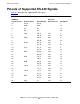
Pinouts of Supported WAN Signals
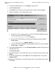
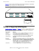
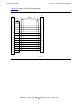
Figure B-1 shows the order of the Ethernet connector pin numbering as viewed when
you are facing the front panel of the SWAN concentrator.
Pinouts of Supported WAN Signals
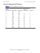
Table B-2, Table B-3, Table B-4, and Table B-5 describe the supported WAN interface
signals for each interface type (RS-232, RS-449, X.21 and V.35). The following list
gives the meaning of each column of these tables:
Figure B-1. 10Base-T RJ-45 Connector Pin Numbering: Front Panel View
Table Column Meaning
WAN Port
Connector Pins
L
ists the pins on the six 50-pin WAN port connectors on
the front panel of the SWAN concentrator.
Generic Name Is a generally recognized name of the supported signal.
Interface Name Describes the name of the signal for the particular
interface.
Electrical
Characteristic
Indicates the electrical characteristics of the signals that
run on the circuit. RS-232 is composed entirely of RS-232
electrical signals. RS-449 is composed of RS-422 and
RS-423 signals. X.21 is composed of RS-422 signals.
V.35 is composed of RS-232 and V.35 signals.
Interface Pin Lists the supported pins for the particular interface.
POWER
10BASE-T
PATH
LNK
TX
COL
RX
LNK
TX
COL
RX
A B
1 2 3 4 5 6 7 8
CLIP 1
CLIP 2
CLIP 3
LINE 0 LINE 0 LINE 0
LINE 1
LINE 1
LINE 1
VST852.vsd