
SWAN Concentrator Installation and Support Guide


Cable Specifications
SWAN Concentrator Installation and Support Guide—429391-006
B-6
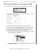
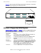
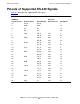
Pinouts of Supported RS-449 Signals
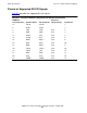
Figure B-3 shows the RS-449 cable design. Pin 50 and 34 are grounded using pin 2
internally in connector P1. Refer to the Interface Select (ISEL Code) on page B-21.
Figure B-3. RS-449 Cable Design
SHIELD
33
2
46
18
5
6
10
11
14
15
19
20
22
23
25
26
28
29
31
32
P1
P2
BLK
3
34
38
42
43
50
39
1
19
15
20
37
4
22
6
24
7
25
9
27
11
29
12
30
13
31
17
35
5
23
8
26
BLK
VST917.vsd