
SWAN Concentrator Installation and Support Guide

Cable Specifications
SWAN Concentrator Installation and Support Guide—429391-006
B-10
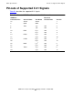
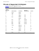
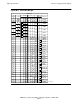
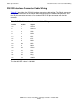
Pinouts of Supported V.35 Signals
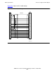
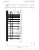
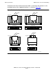
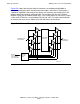
Figure B-5 and Figure B-6 shows the V.35 cable designs. Pin 17 and 34 are grounded
using pin 2 internally in connector P1. Refer to the Interface Select (ISEL Code) on
page B-21.
Figure B-5. V.35 Cable Design
SHIELD
A
B
P
S
R
T
C
D
E
H
F
U
W
Y
AA
V
X
J
33
2
7
8
10
11
12
13
16
17
21
24
27
34
35
36
38
39
40
42
43
44
45
P1
P2
WT
1
WT
2
BLK
BLK
BLK
BLK
BLK
BLK
BLK
VST918.vsd