
TCP/IP Configuration and Management Manual


Configuring the NonStop TCP/IP Subsystem
TCP/IP Configuration and Management Manual—427132-004
3-2
Configuration 1: Startup Files for a Host in a Basic
NonStop TCP/IP Environment
Configuration 1: Startup Files for a Host in a Basic NonStop
TCP/IP Environment
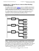
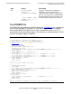
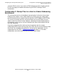
The sample environment shown in Figure 3-1 consists of a backbone communications
link with three industry-standard routers connected to three different networks. These
networks are made up of other NonStop systems. Because IP addresses are Class B,
network-routing decisions are based upon the first two octets of each IP address.
The sample configuration provides the startup files for the NonStop system HOST1.
The specific IP addresses entered in these files appear in boldface. For router
configuration, consult the documentation provided by your vendor.
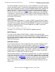
HOST1 is a NonStop system that has two Gigabit Ethernet 4-port ServerNet adapters
(G4SAs). (For more information about configuring G4SAs, see the LAN Configuration
and Management Manual and the Gigabit Ethernet 4-Port Adapter Installation and
Support Guide.) The two G4SAs attached to the same network appear as two separate
hosts to the rest of the network. Although they could be configured using the same
NonStop TCP/IP process ($ZTC0), the sample configuration shows them using
separate NonStop TCP/IP processes ($ZTC0 and $ZTC1).
Figure 3-1. Basic NonStop TCP/IP Environment
007VST .VSD
128.30.128.1 150.50.192.1
150.50.130.2
150.50.130.3
150.50.130.4
128.30.128.2 150.60.64.1
150.60.64.2
150.60.64.3
128.30.128.3 150.70.128.1
150.70.128.2
150.70.128.3
HOST1
HOST2
HOST3
HOST4
HOST5
HOST6
RTR1
RTR2
RTR3
Backbone