
TCP/IP Configuration and Management Manual

Configuring the NonStop TCP/IP Subsystem
TCP/IP Configuration and Management Manual—427132-004
3-6
Configuration 1: Startup Files for a Host in a Basic
NonStop TCP/IP Environment
For the ADD SUBNET command, you can assign the SUBNET name to be anything
you like, provided the name is no more than seven alphanumeric characters long and
begins with an alphabetic character. The DEVICENAME attribute, which specifies the
logical interface (LIF) name associated with the adapter that the NonStop TCP/IP
process will access, is required. (See Hint on page 1-7 for determining an appropriate
LIF.) You can have more than one ServerNet adapter supporting the same NonStop
TCP/IP process. You must have a unique IP address for each ServerNet adapter that
is physically attached to your network. The IP address links the I/O process name and
the NonStop TCP/IP process.
LOOPBACK
When the NonStop TCP/IP process is started, a SUBNET named #LOOP0 is added
automatically. This SUBNET exists to provide loopback capability without requiring the
use of the TCP/IP network. When this #LOOP0 SUBNET is created, it has an address
of 0.0.0.0 in dotted decimal form. For correct operation, the address needs to be
changed by using the command:
ALTER SUBNET #LOOP0, IPADDRESS 127.1
The address 127.1 or 127.0.0.1 is the standard for loopback operation.
ROUTE Objects
The routes are then added. A ROUTE object is added for each remote subnet
destination with which this host will need to communicate. The ROUTE object specifies
the destination network IP address and the router IP address to which this host is
physically connected. You specify the router address in the GATEWAY attribute of the
ADD ROUTE command.
GATEWAY Attribute
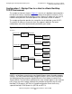
In this sample environment, there are potentially three destination networks to which
HOST1 could communicate, and the router address specified in the GATEWAY
attribute is the same for each route. As you can see from reviewing Figure 3-1
, HOST1
must route a datagram destined for one of those three networks through RTR1, which
has the IP address of 150.50.192.1. This method is especially useful when you have
multiple routers to multiple networks. When all the routing is through a single router,
however, there is a simpler way to set up your routing.
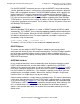
Default routing establishes a single route as the default route. This action is particularly
useful when you know that most of your TCP/IP traffic is going through a single router,
as in the case shown in Example 3-2
. The single route added for the second NonStop
TCP/IP process ($ZTC1) in Figure 3-1
implements default routing. What indicates that
this is a default route is the use of 0.0.0.0 to designate the destination network IP
address. You can add more routes for networks that cannot be reached by using the
default route.